
Overview
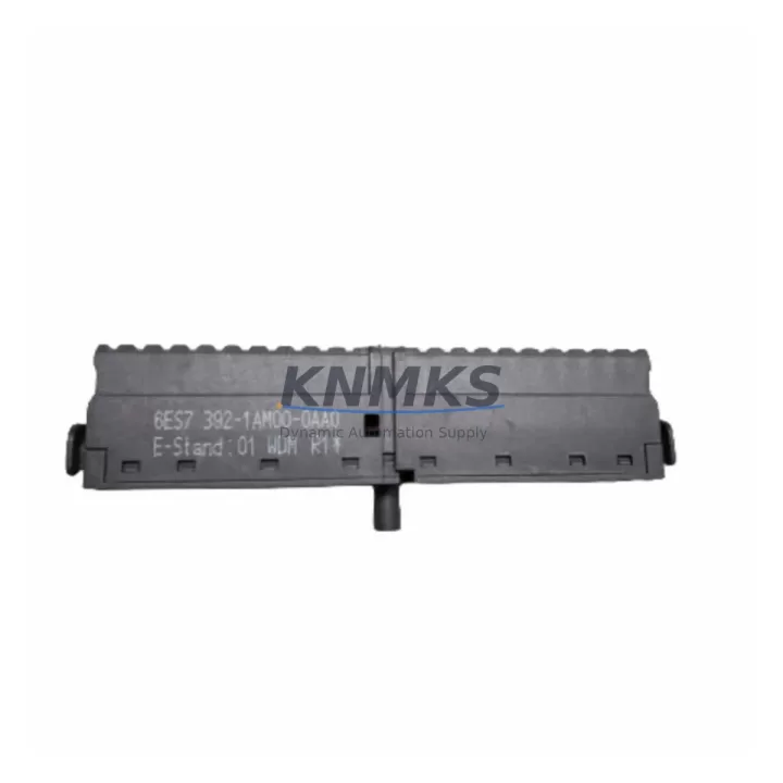
SIEMENS 6ES7392-1AM00-0AA0 Migration-Ready Front Connector for Legacy Control Systems
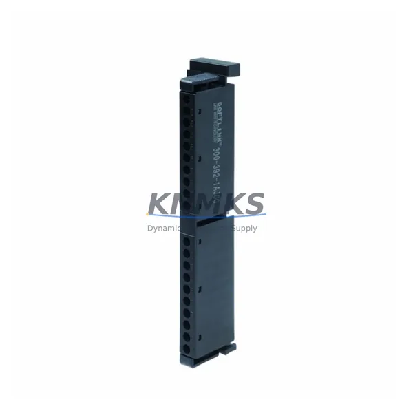
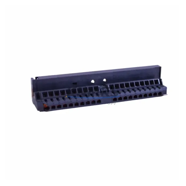
The SIEMENS 6ES7392-1AM00-0AA0 is a 20-pin screw-type front connector designed for SIMATIC S7-300 signal modules (SM). As legacy S7-300 installations approach end-of-life or require panel upgrades, this connector remains a critical interface component — bridging field wiring to SM 321, SM 322, SM 331, and SM 332 I/O modules without requiring re-termination of existing cable looms. Its plug-and-retain mechanical design allows the wired connector to be transferred to a replacement module during a swap, dramatically reducing downtime during corrective maintenance or planned migration.
For engineers managing aging SIMATIC S7-300 control systems, sourcing verified, in-stock front connectors is often the bottleneck that delays otherwise straightforward module replacements. The 6ES7392-1AM00-0AA0 supports up to 20 field terminals with screw-clamp connections rated for 0.25–1.5 mm² conductors, making it compatible with the majority of legacy panel wiring standards still in service across process, discrete, and hybrid automation environments.
When planning a retrofit or module-level replacement, engineers must confirm that the replacement SM module — whether an SM 321 DI 16×DC24V or an SM 331 AI 8×12Bit — shares the same 20-pin front connector footprint. The 6ES7392-1AM00-0AA0 is not compatible with 40-pin modules such as the SM 321 DI 32×DC24V, which requires the 6ES7392-1BM01-0AA0 instead. Verifying connector pin count before ordering prevents installation errors and avoids unnecessary downtime extensions.
In multi-rack S7-300 configurations, the front connector interacts directly with the module’s backplane slot assignment and I/O address mapping. When replacing a failed SM module, the existing 6ES7392-1AM00-0AA0 connector — with its field wiring intact — can be unplugged and re-inserted into the new module, preserving terminal assignments and eliminating re-wiring risk. This is particularly valuable in installations where the STEP 7 or TIA Portal program references fixed I/O addresses tied to physical slot positions on the UR2 or UR1 rack.
For sites migrating from S7-300 to S7-1500 or ET 200MP distributed I/O, the front connector ecosystem changes significantly. The S7-1500 uses a different front connector family (e.g., 6ES7592-1AM00-0XB0 for 35mm modules), and field wiring must be re-terminated. Planning this transition requires a full terminal-by-terminal mapping exercise, cross-referencing the existing S7-300 SM wiring diagrams against the new S7-1500 or ET 200MP module pinouts. The 6ES7392-1AM00-0AA0 remains relevant during the transition period when S7-300 racks are kept operational in parallel with new hardware during phased cutover.
All units are supplied with pre-shipment functional inspection, original or equivalent packaging, and a support terms confirmed by quotation covering manufacturing defects and connector integrity. Stock is available for immediate dispatch.
Migration Compatibility Table
| Parameter | Specification / Recommendation |
|---|---|
| Compatible Modules | S7-300 SM 321, SM 322, SM 331, SM 332 (20-pin variants) |
| Pin Count | 20-pin screw-clamp front connector |
| Conductor Cross-Section | 0.25–1.5 mm² (solid or stranded) |
| Installation Interface | SIMATIC S7-300 UR1 / UR2 / UR2-H rack, DIN rail mount |
| Communication Compatibility | N/A (passive wiring connector; compatible with all S7-300 bus architectures including PROFIBUS DP and MPI) |
| Incompatible Modules | 40-pin SM modules (use 6ES7392-1BM01-0AA0); S7-1500 / ET 200MP (different connector family) |
| Replacement Recommendation | Direct drop-in for all 20-pin S7-300 SM slots; verify pin count before ordering |
| Commissioning Note | Transfer wired connector to new module; no re-termination required if wiring is intact |
| Support terms | 12 months from date of shipment |
Retrofit Planning for Existing Automation Systems
A successful S7-300 retrofit begins with a rack-level audit. Before ordering replacement modules or connectors, document the slot assignments across each UR2 rack, noting which slots carry SM 321 digital input modules, SM 322 digital output modules, SM 331 analog input modules, and SM 332 analog output modules. Each 20-pin slot requires one 6ES7392-1AM00-0AA0 front connector. Cross-check against the existing STEP 7 hardware configuration (HW Config) to confirm that module order numbers, firmware versions, and I/O addresses are consistent with the installed base.
Power budget verification is essential when adding replacement modules to an existing rack. The S7-300 CPU — whether a CPU 315-2 DP, CPU 317-2 PN/DP, or CPU 319-3 PN/DP — supplies backplane current to all SM modules via the rack bus. Adding higher-current-draw replacement modules may require a PS 307 power supply upgrade (e.g., from 5A to 10A) to maintain stable operation. Confirm the total current draw of all installed SMs against the CPU’s backplane current budget before finalizing the BOM.
For systems using PROFIBUS DP for distributed I/O, verify that any replacement SM modules retain the same DP address assignments and GSD file compatibility. If the retrofit includes adding an ET 200S or ET 200M remote I/O station, the IM 153-2 interface module and its associated terminal modules must be sized to match the existing field wiring gauge. Signal isolators may be required at the transition point between legacy 4–20 mA analog loops and new module inputs to prevent ground loop interference.
HMI screens built on SIMATIC WinCC or WinCC flexible reference I/O tags mapped to S7-300 data blocks. When replacing modules, confirm that DB addresses and tag names remain unchanged in the STEP 7 or TIA Portal project to avoid HMI communication faults. If migrating to a new CPU or rack layout, a full tag re-mapping exercise is required before go-live. Programming cables such as the PC Adapter USB A2 or MPI/PROFIBUS adapter should be on-site during commissioning to allow live program monitoring and online diagnostics.
Downtime Control During System Migration
Minimizing unplanned downtime during an S7-300 module replacement requires preparation before the maintenance window opens. The most effective approach is to pre-wire a spare 6ES7392-1AM00-0AA0 front connector with the replacement field wiring in advance, so that the swap is reduced to a connector transfer and module insertion — typically under five minutes per slot. For critical production lines, a hot-standby CPU configuration using the S7-400H or a redundant ET 200M station can maintain control continuity while the primary rack is serviced.
Before powering down the rack, export the current STEP 7 or TIA Portal project to a backup file and document the current I/O force table state. This ensures that any forced outputs or diagnostic overrides are restored correctly after the replacement. Use the CPU’s STOP/RUN switch sequence to perform a controlled shutdown rather than cutting rack power abruptly, which can corrupt the CPU memory card on older firmware versions.
After module insertion and connector re-engagement, perform a structured commissioning check: verify module LED status (SF, BF, DC5V), confirm I/O address recognition in the online hardware diagnostics, and test each channel against the field device before releasing the system to production. For analog SM 331 or SM 332 modules, re-run the channel calibration or scaling verification to confirm that 4–20 mA or 0–10V signal ranges are correctly mapped to engineering units in the PLC program.
Retrofit Support FAQ
Q: Is the 6ES7392-1AM00-0AA0 a direct replacement for all S7-300 front connectors?
A: No. It is specific to 20-pin S7-300 SM modules. For 40-pin modules, the correct part is 6ES7392-1BM01-0AA0. Always verify the pin count of the target module before ordering.
Q: Can I transfer the existing wired connector to a new replacement module?
A: Yes. The 6ES7392-1AM00-0AA0 is designed for this purpose. The connector unlatches from the module and re-engages on the replacement, preserving all field wiring terminations. This is the recommended procedure for minimizing downtime during corrective maintenance.
Q: What pre-shipment testing is performed on these connectors?
A: Each unit undergoes visual inspection, mechanical engagement verification, and terminal continuity checks before dispatch. Units are supplied with a support terms confirmed by quotation covering manufacturing defects and connector integrity failure under normal operating conditions.
Q: Is stock available for immediate shipment?
A: Yes. We maintain inventory of the 6ES7392-1AM00-0AA0 for same-day or next-business-day dispatch. Contact us for volume pricing, lead time confirmation, or urgent order processing.
© 2026 KNMKS. All rights reserved.
Original Source: https://knmks.com
Contact: admin@knmks.com | +86 18359268345
Product Identification
- Brand / Ecosystem
-
SIEMENS
Siemens - Model / Series
-
6ES7392-1AM00-0AA0
SIMATIC Series - Product Family
- Cables & Connectors
- Availability Status
- Available on request after model and quantity confirmation
- Inquiry Type
- B2B RFQ, replacement inquiry and project spare-part request
- Pre-Quote Check
- Exact SKU, brand, series, quantity, nameplate photos and destination country are checked before quotation
System Path
Where this product fits in the KNMKS automation structure.
Specification & Inquiry Focus
- Cable range
- Sensor, servo, network and circular connectors
- Common needs
- Length, pin count, shielding and plug type
- Project support
- Machine wiring and installation kits
Buyer Confirmation
Information KNMKS checks before replying.
- Exact model
- 6ES7392-1AM00-0AA0
- Brand / ecosystem
- SIEMENS
- Product family
- Cables & Connectors
- Application note
- Replacement, maintenance, project build or spare-part list
- Useful photos
- Nameplate, installed unit, cabinet layout or connector side
- Delivery details
- Quantity, destination country and target schedule
Document Support
Files and notes can be confirmed during quotation.
- Product photos or nameplate confirmation when available
- Packing and delivery notes before quotation confirmation
- Support scope and delivery terms confirmed per inquiry
- Export document coordination for qualified B2B requests
Inquiry Support
- Cable length and connector type confirmation
- Servo, sensor and network cable inquiry
- Accessory kits for installation teams
What to Send Us
- Brand and exact model number: SIEMENS 6ES7392-1AM00-0AA0
- Quantity and required delivery time
- Application, replacement requirement or nameplate photo
- Destination country and shipping preference
RFQ Preparation
This is a product inquiry page built for RFQ communication.
Fast Model Check
Send this model to KNMKS for confirmation.
Include quantity, destination country and photos if this is a maintenance replacement. The inquiry will be saved with a reference number after submission.
Brand & Compatibility Note
KNMKS displays automation product information for well-known industrial brand ecosystems and compatible replacement references. Brand names are used for product identification and compatibility reference only; final availability and commercial terms are confirmed per quotation.
 Manufacturing
 Machine Tools
 Packaging
 Energy & Power
 PLCs & Controllers
 HMI & Displays
 Servo Systems
 Variable Frequency Drives