
Overview
Siemens 6ES7392-1AJ00-0AA0 Migration-Ready Front Connector for Legacy Control Systems
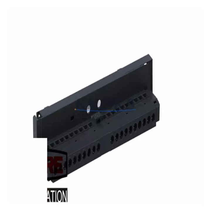
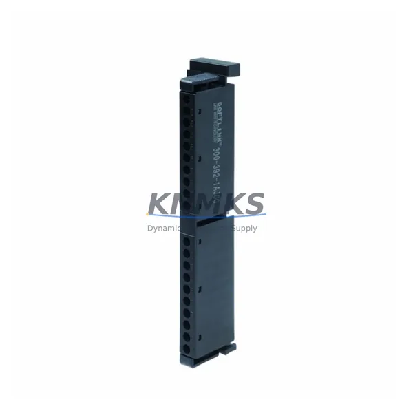
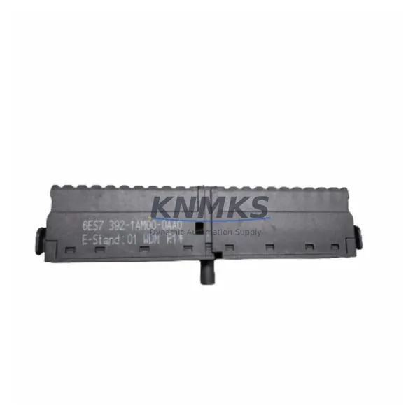
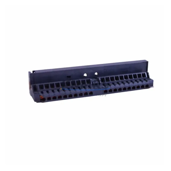
The Siemens 6ES7392-1AJ00-0AA0 is a 20-pin screw-type front connector designed for SIMATIC S7-300 signal modules. As legacy S7-300 installations approach end-of-life or require partial modernization, this front connector remains a critical interface component — enabling field wiring to be preserved and transferred intact during module replacement, rack migration, or control cabinet upgrades. Its plug-and-unplug design allows the entire field wiring harness to be disconnected from the signal module without disturbing individual terminal connections, significantly reducing downtime during planned maintenance or emergency module swap-outs.
In retrofit scenarios where an aging S7-300 system is being partially upgraded — for example, replacing a discontinued SM 321 digital input module or an SM 331 analog input module — the 6ES7392-1AJ00-0AA0 front connector allows the replacement module to accept the existing field wiring immediately. Engineers do not need to re-terminate individual conductors, which eliminates a major source of wiring error and reduces commissioning time on the factory floor. This is especially valuable in high-density control cabinets where access to individual terminals is physically constrained.
When planning a migration from an S7-300 rack to a newer SIMATIC S7-1500 platform or a distributed ET 200SP architecture, the front connector serves as a transition anchor. Field wiring documented against the 6ES7392-1AJ00-0AA0 terminal layout can be systematically re-mapped to the new I/O module’s terminal assignments, providing a structured basis for the wiring adaptation worksheet. During this process, engineers should verify power supply capacity — particularly if the new rack includes a PS 307 or PS 60W power supply module — and confirm that the backplane bus connector spacing and module slot addressing remain consistent with the existing PLC program’s I/O mapping.
For installations where the original S7-300 CPU — such as a CPU 314 or CPU 315-2 DP — is being retained while only the signal modules are refreshed, the 6ES7392-1AJ00-0AA0 ensures backward compatibility at the field wiring level. The screw terminal variant (as opposed to the spring-loaded 6ES7392-1BJ00-0AA0) is preferred in environments with vibration or where periodic re-torquing of terminals is part of the preventive maintenance schedule. Confirm the conductor cross-section range (0.25–1.5 mm²) is compatible with the existing cable specification before reuse.
In communication migration projects — for instance, transitioning from PROFIBUS DP to PROFINET IO — the physical I/O wiring at the front connector level is unaffected by the protocol change. The 6ES7392-1AJ00-0AA0 remains in service while the CP 343-1 communication processor or IM 153-2 interface module is replaced to support the new network topology. This separation of concerns between field wiring and communication infrastructure is a key advantage of the S7-300 modular architecture and should be explicitly documented in the migration plan.
Pre-shipment testing is performed on each unit to verify terminal integrity, connector locking mechanism function, and pin alignment. Units are supplied with a support terms confirmed by quotation covering manufacturing defects. Stock availability is maintained for immediate dispatch to support unplanned outages and emergency replacement scenarios.
Migration Compatibility Table
| Parameter | 6ES7392-1AJ00-0AA0 (This Unit) | Notes / Retrofit Guidance |
|---|---|---|
| Connector Type | 20-pin screw terminal front connector | Compatible with S7-300 signal modules (SM 321, SM 322, SM 331, SM 332, SM 334) |
| Terminal Style | Screw type | Alternative: 6ES7392-1BJ00-0AA0 (spring-loaded); verify site preference before ordering |
| Conductor Cross-Section | 0.25 – 1.5 mm² | Confirm existing cable spec; re-terminate if out of range |
| Backplane Interface | S7-300 module front panel slot | Not compatible with S7-400 or ET 200M modules without adapter |
| Communication Protocol | N/A (field wiring interface only) | Protocol-agnostic; unaffected by PROFIBUS → PROFINET migration |
| Installation Space | Standard S7-300 module footprint | Verify cabinet depth allows front connector swing-out during wiring |
| Replacement Recommendation | Direct drop-in for all 20-pin S7-300 signal modules | No program changes required; I/O address mapping unchanged |
| Firmware Dependency | None | Hardware-only component; no firmware version constraints |
| Pre-Shipment Test | Terminal integrity & locking mechanism verified | Each unit tested before dispatch |
| Support terms | 12 months | Covers manufacturing defects from date of receipt |
Retrofit Planning for Existing Automation Systems
A structured retrofit of an S7-300 control system typically begins with an audit of all installed signal modules and their associated front connectors. Where modules such as the SM 321 DI 32×DC 24V or SM 322 DO 32×DC 24V are being replaced due to discontinuation or failure, the 6ES7392-1AJ00-0AA0 front connector allows the field wiring to be transferred to the replacement module without re-termination. This is particularly important in systems where the original wiring documentation is incomplete or where conductor labeling has degraded over years of operation.
Power supply verification is a mandatory step before any module replacement. The PS 307 5A or PS 307 10A power supply module must be confirmed to have sufficient headroom to support the new module’s current draw, especially if the retrofit involves adding I/O capacity or upgrading to modules with higher power consumption. Similarly, if the rack is being extended using an IM 360/IM 361 expansion interface module pair, the total bus current budget across all racks must be recalculated.
For systems incorporating analog I/O — such as the SM 331 AI 8×13Bit or SM 332 AO 4×12Bit — the front connector’s terminal layout must be cross-referenced against the new module’s channel-to-terminal mapping. Shielding connections and reference potential terminals (M+, M-) should be verified against the original wiring diagram before the connector is transferred. Signal isolators installed upstream of the analog inputs should also be checked for compatibility with the new module’s input impedance.
In control cabinets where an OP 7 or TP 177B HMI panel is connected to the S7-300 CPU via MPI or PROFIBUS, the HMI screen tags referencing I/O addresses must be validated after any module slot reassignment. If the retrofit involves moving a module to a different slot in the rack, the hardware configuration in STEP 7 or TIA Portal must be updated and re-downloaded to the CPU before the HMI is reconnected. Programming cables such as the PC Adapter USB A2 are typically required for this step in field environments without a permanent engineering station connection.
Downtime Control During System Migration
Minimizing unplanned downtime is the primary operational constraint in any S7-300 retrofit. The plug-in design of the 6ES7392-1AJ00-0AA0 front connector is the single most effective hardware feature for achieving this goal: the entire field wiring harness can be disconnected from a failed or end-of-life module in under two minutes and transferred to a pre-tested replacement module without disturbing any individual terminal connection.
Before initiating a hot-swap or planned replacement, the existing PLC program should be backed up from the CPU using STEP 7 or TIA Portal, and the hardware configuration file should be archived. If the replacement module is of the same order number and firmware revision, no hardware configuration change is required and the CPU can resume normal operation immediately after the module is seated and the front connector is reattached. If the module type differs — for example, upgrading from a 16-channel to a 32-channel variant — the hardware configuration must be updated offline and downloaded during the maintenance window.
For systems where continuous process control is required, a parallel wiring strategy can be employed: the replacement module is pre-wired using a second 6ES7392-1AJ00-0AA0 front connector with a duplicate wiring harness, tested offline, and then swapped into the rack during a brief controlled stop. This approach eliminates the risk of wiring errors under time pressure and allows the commissioning engineer to verify signal integrity on the bench before the module enters service. The total controlled stop duration for this procedure is typically under 15 minutes for a single module replacement.
Post-replacement verification should include a full I/O force test of all channels on the replaced module, confirmation of communication link status on the PROFIBUS or PROFINET diagnostic display, and a review of the CPU diagnostic buffer for any hardware fault entries. These steps should be documented in the site maintenance log to support future audits and support requests.
Retrofit Support FAQ
Q: Is the 6ES7392-1AJ00-0AA0 a direct replacement for all 20-pin S7-300 front connectors?
A: Yes. The 6ES7392-1AJ00-0AA0 is the standard 20-pin screw-type front connector for SIMATIC S7-300 signal modules. It is interchangeable with any other 6ES7392-1AJ00-0AA0 unit and is compatible with all S7-300 signal modules that use the 20-pin front connector interface, including SM 321, SM 322, SM 331, SM 332, and SM 334 variants.
Q: Can the existing field wiring be reused when replacing a failed S7-300 signal module?
A: Yes, provided the replacement module uses the same terminal assignment. The front connector retains all field wiring terminations independently of the signal module. Disconnect the front connector from the failed module, seat the replacement module in the rack, and reattach the front connector. No re-termination is required if the module order number is identical. If the module type changes, verify the terminal-to-channel mapping before reconnecting.
Q: What pre-shipment testing is performed, and what does the support terms confirmed by quotation cover?
A: Each unit undergoes terminal integrity verification and locking mechanism function testing before dispatch. The support terms confirmed by quotation cover manufacturing defects in materials and workmanship from the date of receipt. It does not cover damage resulting from incorrect installation, over-torquing of terminals, or use outside the specified conductor cross-section range (0.25–1.5 mm²).
Q: Is stock available for immediate dispatch to support emergency replacement scenarios?
A: Yes. Inventory is maintained specifically to support unplanned outages and emergency spare part requirements. Orders received before the daily dispatch cutoff are processed for same-day shipment. For urgent requirements or bulk procurement for planned maintenance shutdowns, contact the sales team directly to confirm availability and lead time.
© 2026 KNMKS. All rights reserved.
Original Source: https://knmks.com
Contact: admin@knmks.com | +86 18359268345
Product Identification
- Brand / Ecosystem
-
Siemens
Siemens - Model / Series
-
6ES7392-1AJ00-0AA0
SIMATIC Series - Product Family
- Cables & Connectors
- Availability Status
- Available on request after model and quantity confirmation
- Inquiry Type
- B2B RFQ, replacement inquiry and project spare-part request
- Pre-Quote Check
- Exact SKU, brand, series, quantity, nameplate photos and destination country are checked before quotation
System Path
Where this product fits in the KNMKS automation structure.
Specification & Inquiry Focus
- Cable range
- Sensor, servo, network and circular connectors
- Common needs
- Length, pin count, shielding and plug type
- Project support
- Machine wiring and installation kits
Buyer Confirmation
Information KNMKS checks before replying.
- Exact model
- 6ES7392-1AJ00-0AA0
- Brand / ecosystem
- Siemens
- Product family
- Cables & Connectors
- Application note
- Replacement, maintenance, project build or spare-part list
- Useful photos
- Nameplate, installed unit, cabinet layout or connector side
- Delivery details
- Quantity, destination country and target schedule
Document Support
Files and notes can be confirmed during quotation.
- Product photos or nameplate confirmation when available
- Packing and delivery notes before quotation confirmation
- Support scope and delivery terms confirmed per inquiry
- Export document coordination for qualified B2B requests
Inquiry Support
- Cable length and connector type confirmation
- Servo, sensor and network cable inquiry
- Accessory kits for installation teams
What to Send Us
- Brand and exact model number: Siemens 6ES7392-1AJ00-0AA0
- Quantity and required delivery time
- Application, replacement requirement or nameplate photo
- Destination country and shipping preference
RFQ Preparation
This is a product inquiry page built for RFQ communication.
Fast Model Check
Send this model to KNMKS for confirmation.
Include quantity, destination country and photos if this is a maintenance replacement. The inquiry will be saved with a reference number after submission.
Brand & Compatibility Note
KNMKS displays automation product information for well-known industrial brand ecosystems and compatible replacement references. Brand names are used for product identification and compatibility reference only; final availability and commercial terms are confirmed per quotation.
 Manufacturing
 Machine Tools
 Packaging
 Energy & Power
 PLCs & Controllers
 HMI & Displays
 Servo Systems
 Variable Frequency Drives