
Overview
Siemens 6ES7153-2BA01-0XB0 Migration-Ready IM for Legacy ET 200M Systems
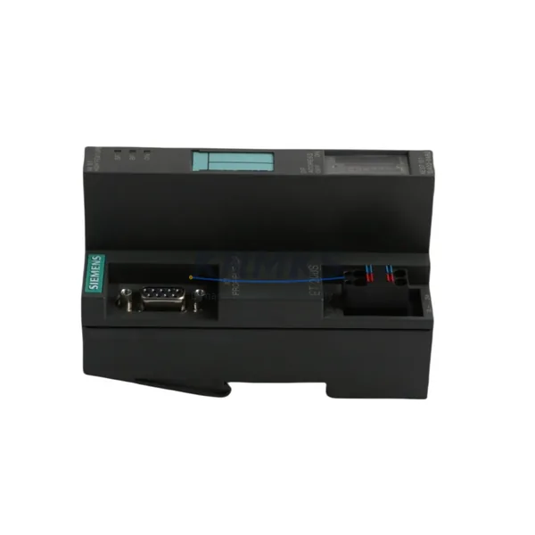
The Siemens 6ES7153-2BA01-0XB0 (IM 153-2) is a PROFIBUS DP interface module designed for the ET 200M distributed I/O station. As legacy automation systems face end-of-life pressures, this module has become a critical component in retrofit projects, discontinued spare part replacement programs, and control cabinet modernization initiatives across process industries, automotive manufacturing, and utility infrastructure. Whether you are replacing a failed IM 153-1 (6ES7153-1AA03-0XB0) or executing a planned migration from an aging S5 or early S7-300 architecture, the 6ES7153-2BA01-0XB0 provides a reliable, verified-compatible upgrade path with minimal disruption to existing field wiring and program logic.
Before committing to a replacement, engineers must carefully evaluate several interdependent factors. Power supply capacity within the control cabinet is the first checkpoint: the ET 200M rack draws power from a dedicated PS 307 or equivalent power supply module, and adding or swapping an IM module may shift the total current budget. Confirm that the existing 24 VDC rail can sustain the IM 153-2 alongside all installed SM signal modules — typically SM 321 digital input, SM 322 digital output, and SM 331 analog input cards — without exceeding the backplane’s rated current. Terminal wiring on the PROFIBUS connector (9-pin Sub-D) must be verified for correct A/B line polarity, bus termination resistor status at segment endpoints, and cable shielding continuity, particularly in environments with high electromagnetic interference from variable frequency drives or large motor starters.
Backplane interface compatibility is non-negotiable. The 6ES7153-2BA01-0XB0 occupies the leftmost slot of the ET 200M rack and communicates with downstream signal modules via the internal S7 backplane bus. If the existing rack is a 6ES7195-1GA00-0XA0 or similar IM 153-series compatible chassis, physical fitment is confirmed. Module slot addressing must be re-verified in the STEP 7 hardware configuration (HW Config) after replacement: the IM’s PROFIBUS node address is set via the integrated rotary switches on the front panel, and this address must match the GSD file entry in the master PLC — typically a Siemens S7-300 CPU such as the CPU 315-2 DP (6ES7315-2AH14-0AB0) or a CP 342-5 communications processor acting as DP master.
Program compatibility review is essential before going live. The replacement IM 153-2 is fully backward compatible with IM 153-1 configurations at the PROFIBUS protocol level, but engineers should validate the GSD file version loaded in the master’s hardware configuration. Mismatched GSD versions can cause diagnostic alarms or prevent the slave station from entering RUN mode. HMI screen updates — particularly on WinCC flexible or TP/OP panels connected via MPI or PROFIBUS — should be tested in simulation mode before live commissioning to confirm that process value displays, alarm triggers, and operator control elements remain correctly mapped to the new module’s I/O addresses.
Communication link integrity across the PROFIBUS segment must be validated with a bus diagnostic tool or the integrated diagnostics in STEP 7 before restarting production. Check the PROFIBUS segment for correct baud rate (typically 1.5 Mbit/s or 12 Mbit/s), verify that no more than 32 nodes share a single segment without a repeater, and confirm that the DP master’s watchdog timer is configured to allow sufficient startup time for the ET 200M station to initialize all downstream SM modules. If the retrofit involves migrating from PROFIBUS DP to PROFINET IO — a common upgrade path when replacing older S7-300 systems with S7-1500 or ET 200SP architectures — a PROFIBUS-to-PROFINET gateway such as the IE/PB Link PN IO (6GK1411-5AB00) may be required to bridge legacy field devices during the transition period.
Installation space confirmation is a practical but frequently overlooked step. The IM 153-2 module dimensions are standard for the ET 200M form factor, but control cabinet depth, DIN rail clearance, and cable management routing must be assessed, especially in retrofit scenarios where the original cabinet was designed for an older, physically different module generation. Firmware version compatibility should also be checked: the 6ES7153-2BA01-0XB0 supports specific firmware revisions that determine available diagnostic functions and PROFIBUS DP-V1 acyclic services. Ensure the firmware version is compatible with the DP master’s software revision before field installation.
On-site commissioning workflow should follow a structured sequence: power down the ET 200M station, remove the old IM module, install the 6ES7153-2BA01-0XB0, set the PROFIBUS address rotary switches to match the original node address, restore power, and monitor the PROFIBUS master’s diagnostic buffer in STEP 7 for any SF (system fault) or BF (bus fault) LEDs. A successful startup is confirmed when the IM’s RUN LED is solid green and all downstream SM modules report no diagnostic errors. Downtime for a like-for-like IM replacement on a prepared system typically ranges from 30 to 90 minutes, depending on cabinet accessibility and the number of signal modules requiring re-initialization.
Every 6ES7153-2BA01-0XB0 unit supplied by KNMKS is sourced from verified supply channels, undergoes pre-shipment functional testing, and is covered by a support terms confirmed by quotation against manufacturing defects and operational failure. Stock is maintained for immediate dispatch to support urgent breakdown replacements and planned retrofit schedules alike.
Migration Compatibility Table
| Parameter | Details |
|---|---|
| SKU / Part Number | 6ES7153-2BA01-0XB0 |
| Module Designation | IM 153-2 |
| Series / Platform | Siemens ET 200M Distributed I/O |
| Interface / Protocol | PROFIBUS DP (DP-V0 / DP-V1) |
| Replaces / Compatible With | 6ES7153-1AA03-0XB0 (IM 153-1), 6ES7153-2AA02-0XB0 |
| Rack Compatibility | ET 200M rack (e.g. 6ES7195-1GA00-0XA0) |
| Backplane Bus | S7 internal backplane bus |
| PROFIBUS Address Setting | Rotary switch on front panel (1–125) |
| Supply Voltage | 24 VDC (via backplane / PS 307) |
| Installation | DIN rail, leftmost slot of ET 200M rack |
| Compatible DP Masters | S7-300 CPU 315-2 DP, CPU 317-2 DP, CP 342-5, S7-400 DP masters |
| Commissioning Tool | Siemens STEP 7 v5.x (HW Config + GSD file) |
| Firmware Compatibility | Verify firmware revision against DP master software version |
| Downtime Estimate | 30–90 minutes (like-for-like replacement) |
| Origin | Germany |
| Support terms | 12 Months — KNMKS Pre-Shipment Tested |
Retrofit Planning for Existing Automation Systems
A successful ET 200M retrofit begins well before the maintenance window opens. Start by auditing the full rack configuration: document every SM module installed — including SM 321 (16DI), SM 322 (16DO), SM 331 (8AI), and SM 332 (4AO) cards — along with their slot positions, I/O addresses, and wiring terminal assignments. This documentation becomes the reference baseline for post-replacement verification. The PS 307 5A power supply module feeding the rack should be load-tested to confirm it can sustain the 6ES7153-2BA01-0XB0 alongside all signal modules without voltage droop under peak I/O switching loads.
For systems where the PROFIBUS segment also carries communications to other field devices — such as Siemens ET 200S stations, SINAMICS G120 drives, or third-party PROFIBUS slaves — the bus topology must be mapped before any module swap. Removing the ET 200M station from the bus, even briefly, can trigger watchdog faults in the DP master and cause cascading alarms in the SCADA or DCS layer. Pre-staging the replacement IM 153-2 with the correct PROFIBUS node address set on the rotary switches eliminates one source of commissioning error and reduces the time the station is offline.
If the retrofit scope extends beyond a single IM module replacement — for example, when upgrading an entire control cabinet from S7-300 to S7-1500 with ET 200SP I/O — the migration path typically involves running the new and old systems in parallel during a transition period. In this scenario, a CP 343-1 Ethernet communications processor or an IE/PB Link gateway can bridge PROFIBUS field devices to the new PROFINET backbone, preserving field wiring investments while the control logic is ported and validated. Programming cables such as the PC Adapter USB A2 (6ES7972-0CB20-0XA0) are essential for connecting a laptop to the S7-300 backplane MPI port during on-site firmware checks and program uploads without requiring a full network infrastructure.
Signal isolation requirements should be assessed for analog I/O channels connected to field transmitters in hazardous areas or across long cable runs. Signal isolators or barriers installed between the SM 331 analog input module and field instruments protect the backplane from ground loops and transient voltages that could corrupt analog readings or damage module inputs during the retrofit process.
Downtime Control During System Migration
Minimizing production downtime during an ET 200M IM module replacement requires a disciplined pre-work protocol. Before the maintenance window, upload and archive the current S7-300 program from the CPU using STEP 7 — including all data blocks, organization blocks, and hardware configuration — to a secure offline backup. This ensures that if the replacement triggers unexpected behavior, the original program state can be restored within minutes rather than hours.
During the swap, maintain field control continuity where possible by placing the affected process loops in manual mode at the DCS or SCADA level before powering down the ET 200M station. Operators should be briefed on manual override procedures for critical control loops — particularly flow control valves, pump starters, and temperature regulators — that will lose automatic control during the IM replacement window. For safety-instrumented systems, confirm with the SIS engineer that the replacement activity is covered by a management of change (MOC) procedure and that safety functions remain active or are bypassed according to the site’s functional safety plan.
Post-replacement, the commissioning sequence should be executed systematically: restore power, observe the IM 153-2 LED status (RUN = green, no BF/SF), confirm PROFIBUS communication in the master’s diagnostic buffer, force-test a representative sample of digital and analog I/O points from STEP 7 to verify correct signal routing, and then release the station to automatic control. Document the as-found and as-left conditions, including PROFIBUS address, firmware version, and any GSD file changes, in the plant’s maintenance management system. This record supports future audits and accelerates the next replacement cycle if needed.
Retrofit Support FAQ
Q1: Is the 6ES7153-2BA01-0XB0 a direct drop-in replacement for the IM 153-1 (6ES7153-1AA03-0XB0)?
At the physical and PROFIBUS protocol level, yes — both modules occupy the same rack slot and communicate via PROFIBUS DP. However, the IM 153-2 supports DP-V1 acyclic services in addition to DP-V0 cyclic data exchange, which the IM 153-1 does not. If your DP master’s hardware configuration was built with the IM 153-1 GSD file, you will need to update the HW Config in STEP 7 to use the IM 153-2 GSD file and re-download the configuration to the CPU. No field wiring changes are required.
Q2: What pre-shipment testing does KNMKS perform on the 6ES7153-2BA01-0XB0?
Each unit undergoes functional power-on testing to verify PROFIBUS communication initialization, LED status indication, and backplane bus integrity before dispatch. Units are inspected for physical condition, connector integrity, and firmware version documentation. A test report is available on request for quality-critical procurement processes.
Q3: How do I verify PROFIBUS address and GSD file compatibility before installation?
Set the PROFIBUS node address on the IM 153-2 rotary switches to match the address assigned in the DP master’s HW Config before installing the module. In STEP 7 HW Config, confirm that the slave station entry uses the correct GSD file for the 6ES7153-2BA01-0XB0 (SIEM80B3.GSD or equivalent). Compile and download the updated hardware configuration to the CPU, then power up the ET 200M station and check the PROFIBUS master’s diagnostic buffer for a clean station entry with no fault codes.
Q4: What is the support terms coverage and what does it include?
All 6ES7153-2BA01-0XB0 units supplied by KNMKS carry a support terms confirmed by quotation from the date of shipment. The support terms covers manufacturing defects and operational failure under normal industrial operating conditions. It does not cover damage resulting from incorrect installation, overvoltage events, or unauthorized modification. Support requests are processed with a replacement unit dispatched upon receipt and inspection of the returned module. Contact admin@knmks.com to initiate a support terms claim.
© 2026 KNMKS. All rights reserved.
Original Source: https://knmks.com
Contact: admin@knmks.com | +86 18359268345
Product Identification
- Brand / Ecosystem
-
Siemens
Siemens - Model / Series
-
6ES7153-2BA01-0XB0
SIMATIC Series - Product Family
- Relays & Interface
- Availability Status
- Available on request after model and quantity confirmation
- Inquiry Type
- B2B RFQ, replacement inquiry and project spare-part request
- Pre-Quote Check
- Exact SKU, brand, series, quantity, nameplate photos and destination country are checked before quotation
System Path
Where this product fits in the KNMKS automation structure.
Specification & Inquiry Focus
- Interface range
- Relays, isolation and signal modules
- Common needs
- Coil voltage and contact rating
- Project support
- Panel wiring and signal protection
Buyer Confirmation
Information KNMKS checks before replying.
- Exact model
- 6ES7153-2BA01-0XB0
- Brand / ecosystem
- Siemens
- Product family
- Relays & Interface
- Application note
- Replacement, maintenance, project build or spare-part list
- Useful photos
- Nameplate, installed unit, cabinet layout or connector side
- Delivery details
- Quantity, destination country and target schedule
Document Support
Files and notes can be confirmed during quotation.
- Product photos or nameplate confirmation when available
- Packing and delivery notes before quotation confirmation
- Support scope and delivery terms confirmed per inquiry
- Export document coordination for qualified B2B requests
Inquiry Support
- Relay base and module matching
- Signal isolation and protection options
- Panel accessory inquiry support
What to Send Us
- Brand and exact model number: Siemens 6ES7153-2BA01-0XB0
- Quantity and required delivery time
- Application, replacement requirement or nameplate photo
- Destination country and shipping preference
RFQ Preparation
This is a product inquiry page built for RFQ communication.
Fast Model Check
Send this model to KNMKS for confirmation.
Include quantity, destination country and photos if this is a maintenance replacement. The inquiry will be saved with a reference number after submission.
Brand & Compatibility Note
KNMKS displays automation product information for well-known industrial brand ecosystems and compatible replacement references. Brand names are used for product identification and compatibility reference only; final availability and commercial terms are confirmed per quotation.
 Manufacturing
 Machine Tools
 Packaging
 Energy & Power
 PLCs & Controllers
 HMI & Displays
 Servo Systems
 Variable Frequency Drives