
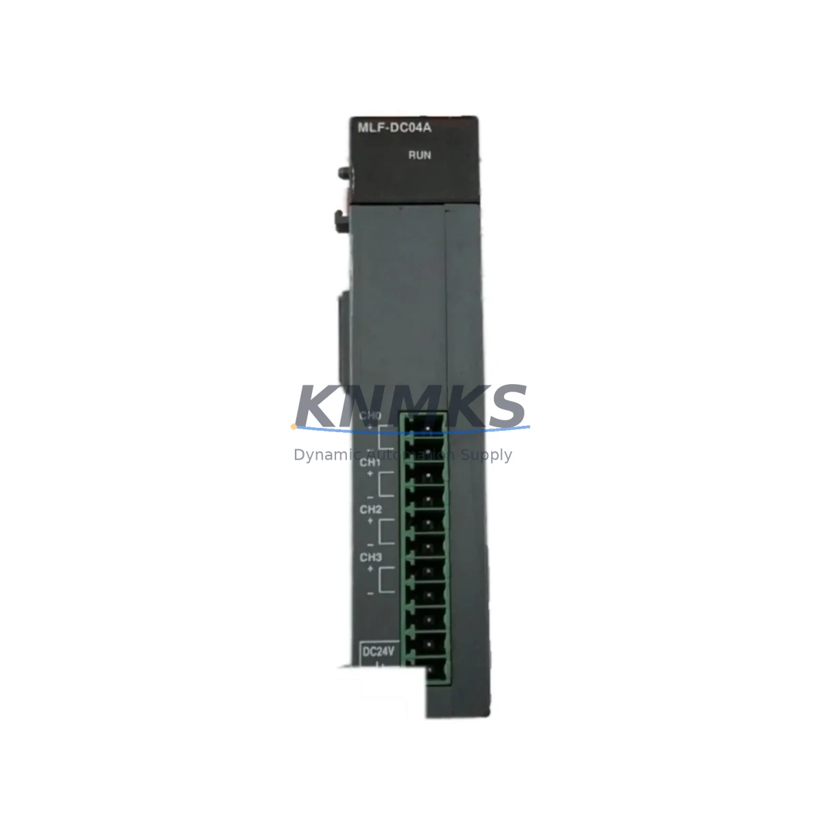
Overview
Honeywell MLF-DC04A Migration-Ready Analog Output Module: Legacy DCS Retrofit and Control System Upgrade
The Honeywell MLF-DC04A is a 4-channel analog output module engineered for the MLF Series Distributed Control System (DCS) platform. As legacy Honeywell MLF Series installations approach end-of-life and original spare parts become increasingly scarce, the MLF-DC04A remains one of the most critical components for sustaining continuous process control in energy, petrochemical, manufacturing, and infrastructure environments. KNMKS maintains verified inventory of the MLF-DC04A to support planned retrofits, emergency replacements, and long-term maintenance contracts.
For engineers managing aging control architectures, the MLF-DC04A delivers 4-channel 4–20 mA or 0–10 V analog output capability, interfacing directly with field actuators, control valves, variable frequency drives, and positioners. Its backplane-mounted form factor integrates seamlessly into existing MLF Series racks without mechanical modification, making it the preferred choice for minimizing downtime during unplanned failures or scheduled upgrade windows.
When planning a replacement or retrofit, engineers must verify several critical parameters before installation: confirm the power supply capacity of the existing MLF rack, as the DC04A draws regulated DC power from the backplane bus and any marginal power headroom must be assessed before adding or swapping modules. Terminal wiring assignments should be cross-referenced against the original I/O drawing set, particularly for field loops that may have been re-terminated during previous maintenance cycles. Backplane slot addressing must be confirmed in the controller configuration to ensure the replacement module is recognized at the correct logical address without requiring a full program download.
Program compatibility is a key concern in any MLF Series migration. The analog output scaling, engineering unit conversion, and alarm limit parameters stored in the controller database must be validated against the replacement module’s channel configuration. If the site is running Honeywell’s legacy engineering workstation software, a configuration export and re-import procedure should be completed prior to module swap to protect the original control logic. HMI faceplate displays tied to the analog output channels should be tested in simulation mode before live commissioning to confirm that trend displays, setpoint write-back, and alarm annunciation remain intact.
Communication link integrity is equally important. In MLF Series architectures, the analog output module communicates with the controller over the internal backplane bus. Any firmware version mismatch between the replacement MLF-DC04A and the installed controller firmware baseline should be identified during pre-commissioning checks. KNMKS provides firmware version documentation with each shipment to support compatibility verification before the module is installed in the field.
Installation space confirmation is straightforward for like-for-like replacements, as the MLF-DC04A occupies a standard MLF Series single-width slot. However, for sites undertaking a broader control cabinet upgrade — for example, migrating from a standalone MLF rack to a hybrid architecture incorporating modern I/O subsystems — the physical envelope of the new mounting arrangement must be verified against the existing cabinet dimensions and cable management infrastructure.
KNMKS ships each MLF-DC04A with a support terms confirmed by quotation covering manufacturing defects and functional performance. All units undergo pre-shipment functional testing including channel-by-channel output verification across the full analog range, backplane interface continuity checks, and visual inspection for connector integrity. Test records are available upon request for quality documentation requirements.
Migration Compatibility Table
| Parameter | MLF-DC04A Specification | Retrofit / Migration Note |
|---|---|---|
| Output Channels | 4-channel analog output | Verify field loop count matches channel assignment in controller config |
| Output Signal | 4–20 mA / 0–10 V (site-dependent) | Confirm signal type matches existing field wiring and actuator input spec |
| Backplane Interface | MLF Series standard backplane connector | Direct drop-in; no mechanical adapter required for same-series rack |
| Power Supply | Backplane DC bus powered | Assess rack power budget before replacement; check MLF power supply module load capacity |
| Slot Addressing | Configured via controller database | Confirm slot address in engineering workstation before module insertion |
| Firmware Compatibility | MLF Series controller firmware dependent | Match firmware baseline; documentation provided with shipment |
| Communication Protocol | Internal MLF backplane bus | No external protocol configuration required for like-for-like replacement |
| Installation Footprint | Single-width MLF Series slot | Confirm slot availability in rack; no cabinet modification for standard swap |
| Replacement Scope | Direct replacement for MLF-DC04A | Suitable for emergency replacement and planned retrofit windows |
| Support terms | support terms confirmed by quotation | Covers manufacturing defects and functional performance; test records available |
Retrofit Planning for Existing Automation Systems
A successful MLF-DC04A retrofit begins well before the module arrives on site. Engineers should compile the existing I/O list, loop drawings, and controller configuration backup as the baseline reference package. In many MLF Series installations, the analog output module works in close coordination with the Honeywell MLF-AI04A analog input module, which handles the feedback signals from field transmitters that close the control loop. Both modules must be confirmed operational before commissioning any analog control loop after a replacement.
The rack and backplane infrastructure should also be inspected during the retrofit window. MLF Series backplanes can develop connector wear after years of service, and a module swap is an appropriate time to clean and inspect the backplane slot contacts. If the site is running an MLF Series power supply module near its rated capacity, the retrofit plan should include a power audit to confirm that the replacement DC04A and any other modules in the rack remain within the power supply’s continuous output rating.
For sites that are simultaneously upgrading their HMI infrastructure — for example, migrating from legacy Honeywell operator stations to a modern SCADA platform — the analog output channel tags must be remapped in the new HMI configuration. This is particularly important for control loops where the HMI provides the remote setpoint write-back to the analog output channel. Testing the setpoint write path from the new HMI to the MLF-DC04A output channel should be a mandatory step in the commissioning checklist.
In installations where the MLF Series DCS communicates with upstream systems via a Honeywell data highway or OPC server interface, the analog output module’s channel data should be verified in the OPC tag browser after replacement to confirm that live values are being published correctly. If the site uses a signal isolator or loop-powered barrier between the MLF-DC04A output and the field actuator — common in hazardous area installations — the isolator’s input impedance and loop supply voltage must be confirmed compatible with the module’s output drive capability.
For broader system migrations where the MLF Series is being partially replaced by a modern controller platform, an I/O marshalling panel or signal conversion module may be required to bridge the legacy MLF analog outputs to the new controller’s I/O bus. In these hybrid architectures, the MLF-DC04A can continue to serve its original field loops while the migration is completed in phases, reducing the scope of any single cutover window and protecting production continuity.
Downtime Control During System Migration
Minimizing downtime during an MLF-DC04A replacement requires a structured pre-commissioning sequence. Before removing the failed or end-of-life module, the control system should be placed in manual mode for all loops served by the DC04A channels, with field operators stationed at the relevant control valves or actuators to maintain process stability during the swap interval. The controller configuration backup should be verified current and stored on an offline engineering workstation before the module is removed from the backplane.
Module insertion should be performed with the rack powered where the controller firmware and site safety procedures permit hot-swap operation. If the MLF Series installation requires a rack power cycle for module recognition, the outage window should be coordinated with the operations team and all affected control loops should be confirmed in manual or local control before power is removed. After module insertion and power restoration, the controller should be monitored for module recognition alarms and the analog output channels should be verified against known engineering unit values before returning loops to automatic control.
Original program logic is preserved throughout a like-for-like MLF-DC04A replacement, as the controller database references the slot address rather than the physical module serial number. No program download is required for a standard replacement, which significantly reduces the commissioning time and eliminates the risk of inadvertent logic changes during the outage window. HMI displays should be monitored for correct value update and alarm state after the module is returned to service, and a short observation period under automatic control is recommended before the retrofit is formally closed out.
KNMKS recommends maintaining at least one spare MLF-DC04A in the site’s critical spare parts inventory to support emergency replacement without lead time dependency. For sites with multiple MLF Series racks, a pooled spare strategy — where a single spare module covers multiple racks of the same configuration — can reduce inventory carrying cost while maintaining acceptable response time for unplanned failures.
Retrofit Support FAQ
Q1: Is the MLF-DC04A a direct drop-in replacement for the original Honeywell MLF Series analog output module?
Yes. The MLF-DC04A is designed as a direct replacement for the original MLF Series 4-channel analog output module. It uses the same backplane connector, occupies the same single-width slot, and is recognized by the controller at the same logical address without requiring configuration changes. KNMKS verifies compatibility before shipment and provides firmware documentation to support pre-installation checks.
Q2: What pre-commissioning checks are required before installing the replacement module?
Engineers should confirm the rack power budget, verify the slot address in the controller configuration, back up the current controller database, and review the terminal wiring against the original loop drawings. If the site uses signal isolators or loop-powered barriers on the analog output channels, the isolator input specifications should be confirmed compatible with the MLF-DC04A output drive capability before installation.
Q3: Does KNMKS provide functional testing documentation with each MLF-DC04A shipment?
Yes. Each unit undergoes pre-shipment functional testing including channel-by-channel analog output verification, backplane interface continuity checks, and visual inspection. Test records are available upon request and can be included with the shipment documentation for quality assurance and incoming inspection requirements.
Q4: What support terms and supply terms apply to the MLF-DC04A?
All MLF-DC04A units supplied by KNMKS carry a support terms confirmed by quotation covering manufacturing defects and functional performance from the date of shipment. KNMKS maintains verified inventory to support both emergency replacement orders and planned retrofit procurement. For sites requiring long-term supply commitments or blanket order arrangements, contact the KNMKS sales team to discuss stocking agreements and lead time guarantees.
© 2026 KNMKS. All rights reserved.
Original Source: https://knmks.com
Contact: admin@knmks.com | +86 18359268345
Product Identification
- Brand / Ecosystem
-
Honeywell
Honeywell - Model / Series
- MLF-DC04A
- Product Family
- PLCs & Controllers
- Availability Status
- Available on request after model and quantity confirmation
- Inquiry Type
- B2B RFQ, replacement inquiry and project spare-part request
- Pre-Quote Check
- Exact SKU, brand, series, quantity, nameplate photos and destination country are checked before quotation
System Path
Where this product fits in the KNMKS automation structure.
Specification & Inquiry Focus
- Control platform
- PLC, PAC and modular controllers
- Common needs
- CPU, rack, power and I/O expansion
- Project support
- Replacement, cabinet build and maintenance
Buyer Confirmation
Information KNMKS checks before replying.
- Exact model
- MLF-DC04A
- Brand / ecosystem
- Honeywell
- Product family
- PLCs & Controllers
- Application note
- Replacement, maintenance, project build or spare-part list
- Useful photos
- Nameplate, installed unit, cabinet layout or connector side
- Delivery details
- Quantity, destination country and target schedule
Document Support
Files and notes can be confirmed during quotation.
- Product photos or nameplate confirmation when available
- Packing and delivery notes before quotation confirmation
- Support scope and delivery terms confirmed per inquiry
- Export document coordination for qualified B2B requests
Inquiry Support
- Model cross-checking before quotation
- CPU, power, rack and expansion module matching
- Support for replacement and project inquiry
What to Send Us
- Brand and exact model number: Honeywell MLF-DC04A
- Quantity and required delivery time
- Application, replacement requirement or nameplate photo
- Destination country and shipping preference
RFQ Preparation
This is a product inquiry page built for RFQ communication.
Fast Model Check
Send this model to KNMKS for confirmation.
Include quantity, destination country and photos if this is a maintenance replacement. The inquiry will be saved with a reference number after submission.
Brand & Compatibility Note
KNMKS displays automation product information for well-known industrial brand ecosystems and compatible replacement references. Brand names are used for product identification and compatibility reference only; final availability and commercial terms are confirmed per quotation.
 Manufacturing
 Machine Tools
 Packaging
 Energy & Power
 HMI & Displays
 Servo Systems
 Variable Frequency Drives
 Sensors