
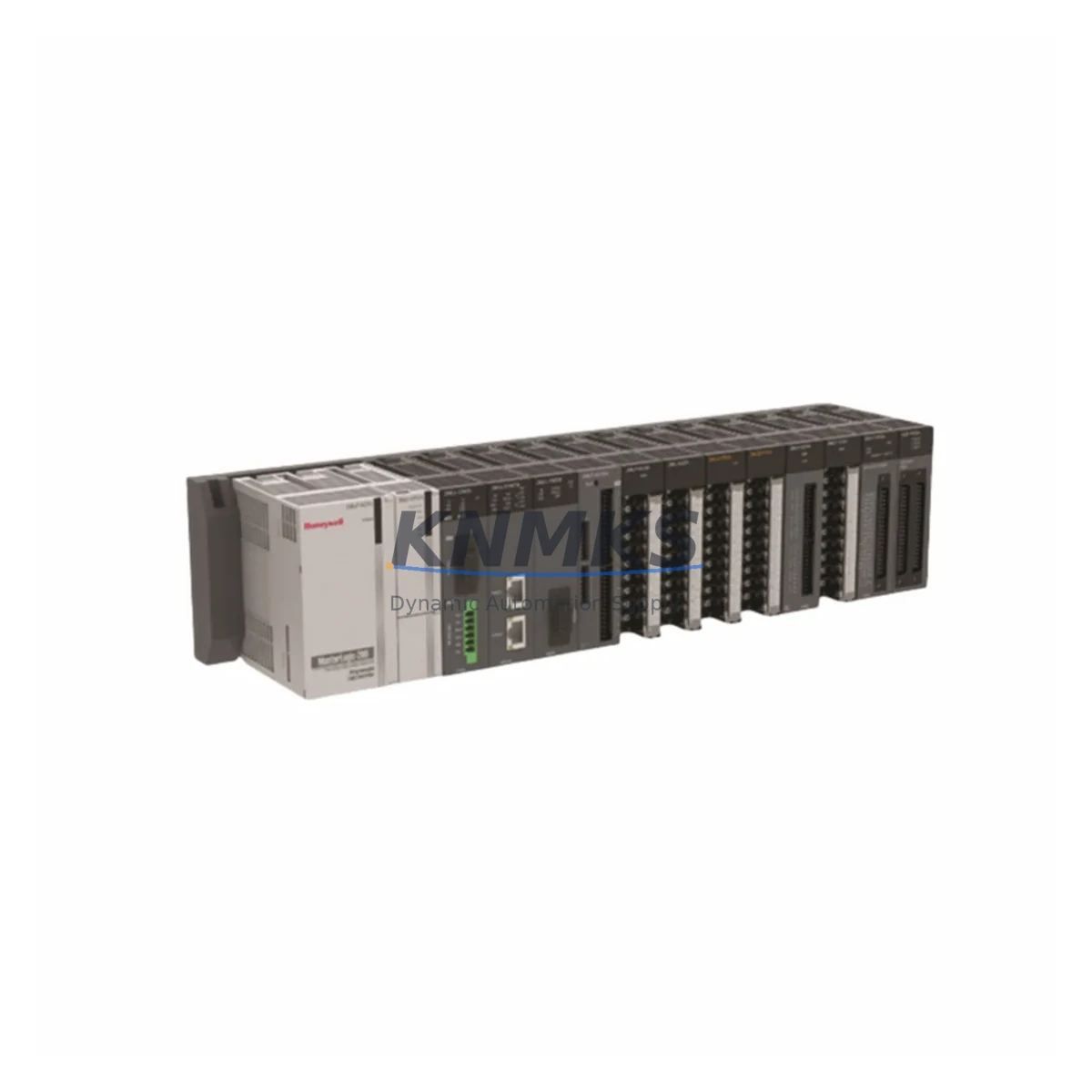
Overview
Honeywell 900R04-0300 Migration-Ready Redundancy Module for Legacy Control Systems
The Honeywell 900R04-0300 is a migration-ready redundancy module engineered for the HC900 Hybrid Controller platform, purpose-built to support legacy system upgrades, discontinued spare part replacement, and control cabinet modernization projects. As aging DCS and PLC infrastructures approach end-of-life, the 900R04-0300 provides a reliable, drop-in compatible solution that preserves existing program logic, minimizes retrofit risk, and extends the operational lifespan of HC900-based control systems without requiring a full platform migration.
For facilities running legacy HC900 configurations with older redundancy architectures, the 900R04-0300 addresses the critical challenge of sourcing discontinued modules while maintaining system integrity. Its compatibility with the HC900 backplane and rack infrastructure means engineers can replace failed or end-of-life redundancy modules without redesigning the control cabinet layout, re-engineering terminal wiring, or rewriting application programs. The module supports Ethernet-based communication links between primary and secondary controllers, enabling seamless switchover logic that protects process continuity during planned maintenance or unplanned fault events.
Before installation, engineers should verify power supply capacity within the existing HC900 rack — particularly when the 900R04-0300 is being added to a chassis already populated with I/O modules such as the 900G32-0101 analog input module or the 900B08-0101 digital output module. Backplane slot addressing must be confirmed against the existing controller configuration to avoid address conflicts that could disrupt the redundancy handshake sequence. Terminal wiring from the primary controller to the redundancy module should be inspected for correct shielding and grounding, especially in high-noise industrial environments where signal integrity affects switchover reliability.
Program compatibility is a key consideration during retrofit planning. The HC900 Designer software configuration file must be reviewed to confirm that the redundancy parameters — including switchover delay, heartbeat interval, and synchronization mode — are correctly mapped to the 900R04-0300 hardware revision. If the existing system was previously running an older firmware version, a controlled firmware upgrade sequence should be planned to ensure the primary controller, the 900R04-0300, and any connected HC900 communication modules such as the 900CS-0001 Ethernet communication module are operating on compatible firmware builds before live switchover testing is performed.
HMI screen configurations linked to redundancy status tags should also be validated. In systems where the HC900 is integrated with a Honeywell Experion PKS supervisory layer or a third-party SCADA platform via Modbus TCP or OPC-DA, the redundancy status data points must be re-mapped if the module slot address has changed during the retrofit. Communication link integrity between the primary and secondary HC900 controllers should be verified using the HC900 Designer diagnostic tools prior to returning the system to automatic mode.
Installation space within the control cabinet must be confirmed before ordering. The 900R04-0300 occupies a dedicated redundancy slot on the HC900 rack and does not share space with standard I/O modules. In retrofit scenarios where the existing rack is fully populated, engineers may need to evaluate whether a rack expansion using an HC900 expansion chassis is required, or whether a rack reconfiguration — relocating lower-priority I/O modules — can free the necessary slot without impacting the overall I/O count or wiring schedule.
Migration Compatibility Table
| Parameter | Details |
|---|---|
| SKU / Part Number | 900R04-0300 |
| Brand / Manufacturer | Honeywell |
| Series / Platform | HC900 Hybrid Controller |
| Module Function | Controller Redundancy Module |
| Backplane Interface | HC900 Rack Backplane (dedicated redundancy slot) |
| Communication Link | Ethernet (primary–secondary redundancy link) |
| Protocol Compatibility | Modbus TCP, OPC-DA (via HC900 communication modules) |
| Firmware Compatibility | Verify HC900 Designer firmware revision before installation |
| Replacement Scope | Direct replacement for legacy HC900 redundancy modules (end-of-life / discontinued) |
| Installation Requirement | Dedicated redundancy slot; confirm rack slot availability before installation |
| Power Requirement | Supplied via HC900 rack backplane; verify rack PSU capacity |
| Wiring Adaptation | No terminal rewiring required for direct slot replacement |
| Program Compatibility | HC900 Designer configuration file; verify redundancy parameter mapping |
| HMI Integration | Re-map redundancy status tags if slot address changes during retrofit |
| Pre-Shipment Testing | Yes — functional test performed before dispatch |
| Support terms | 12 Months |
| Origin | United States |
| Dispatch | global delivery details confirmed by RFQ; multi-region stock available |
Retrofit Planning for Existing Automation Systems
A successful HC900 redundancy retrofit begins with a thorough audit of the existing control cabinet. Engineers should document the current rack population, including the positions of the HC900 primary controller, power supply modules, and all installed I/O modules such as analog input cards and digital output cards, before determining the target slot for the 900R04-0300. In systems where the HC900 rack is shared with communication infrastructure — for example, a 900CS-0001 Ethernet communication module handling Modbus TCP traffic to field devices — the retrofit plan must account for the communication module’s slot position and ensure that the redundancy module installation does not disrupt active communication paths.
Power budget verification is a non-negotiable step. The HC900 rack power supply must have sufficient headroom to support the 900R04-0300 in addition to all existing modules. If the rack is operating near its power supply limit, a power supply upgrade or load redistribution across multiple racks may be required before the redundancy module can be safely installed. Signal isolators installed on analog I/O channels should also be reviewed to confirm that their output signals remain within the input range of the HC900 analog modules after any rack reconfiguration.
For systems integrating the HC900 with Honeywell Experion PKS or third-party SCADA platforms, the redundancy switchover behavior must be tested in a controlled environment before live deployment. Programming cables and HC900 Designer software are required for configuration upload, parameter verification, and post-installation diagnostic checks. Ensuring that the 900R04-0300 firmware version is aligned with the primary controller firmware is essential to prevent synchronization errors during the initial redundancy handshake.
Downtime Control During System Migration
Minimizing unplanned downtime is the primary objective of any HC900 redundancy retrofit. The 900R04-0300 supports hot-standby redundancy architecture, which means the secondary controller continuously mirrors the primary controller’s program state. In the event of a primary controller fault, the switchover to the secondary controller occurs within the configured switchover delay window — typically within one scan cycle — without interrupting the process control loop or requiring operator intervention.
To protect the original program logic during the retrofit, engineers should create a full backup of the HC900 Designer configuration file before any hardware changes are made. This backup serves as the recovery baseline if the retrofit encounters unexpected compatibility issues. The existing I/O module wiring should remain undisturbed during the redundancy module installation, as terminal rewiring introduces the risk of wiring errors that could cause process upsets or safety system activations.
Field commissioning should follow a structured sequence: power-on verification, redundancy link establishment, synchronization confirmation, and controlled switchover testing under simulated fault conditions. Communication links to SCADA and HMI systems should be monitored throughout the commissioning process to confirm that redundancy status tags are updating correctly and that the supervisory system is correctly interpreting the switchover events. Once commissioning is complete, the system should be returned to automatic mode with the redundancy status confirmed as active before the maintenance window is closed.
Retrofit Support FAQ
Q: Is the 900R04-0300 a direct replacement for the discontinued HC900 redundancy module in my existing rack?
A: Yes. The 900R04-0300 is designed as a direct slot replacement for legacy HC900 redundancy modules. No terminal rewiring is required for a like-for-like slot replacement. Verify the rack slot address and firmware version compatibility using HC900 Designer before installation.
Q: What commissioning steps are required after installing the 900R04-0300?
A: After physical installation, connect the HC900 Designer programming cable, upload the existing configuration file, verify redundancy parameter settings (switchover delay, heartbeat interval, synchronization mode), and perform a controlled switchover test. Confirm that SCADA and HMI redundancy status tags are updating correctly before returning the system to automatic mode.
Q: How do I confirm wiring and backplane compatibility before installation?
A: Review the HC900 rack wiring diagram and confirm that the target slot is a dedicated redundancy slot. Verify that the rack power supply has sufficient capacity to support the 900R04-0300. No additional terminal wiring is required for a direct slot replacement; however, the Ethernet redundancy link cable between the primary and secondary controllers must be inspected for integrity.
Q: What support terms and pre-shipment testing does the 900R04-0300 include?
A: Every 900R04-0300 unit is functionally tested before dispatch to verify module operation and communication link integrity. A support terms confirmed by quotation is included from the date of shipment, covering manufacturing defects and functional failures under normal operating conditions. Multi-region stock is maintained to support emergency replacement requirements with fast global dispatch.
© 2026 KNMKS. All rights reserved.
Original Source: https://knmks.com
Contact: admin@knmks.com | +86 18359268345
Product Identification
- Brand / Ecosystem
-
Honeywell
Honeywell - Model / Series
- 900R04-0300
- Product Family
- PLCs & Controllers
- Availability Status
- Available on request after model and quantity confirmation
- Inquiry Type
- B2B RFQ, replacement inquiry and project spare-part request
- Pre-Quote Check
- Exact SKU, brand, series, quantity, nameplate photos and destination country are checked before quotation
System Path
Where this product fits in the KNMKS automation structure.
Specification & Inquiry Focus
- Control platform
- PLC, PAC and modular controllers
- Common needs
- CPU, rack, power and I/O expansion
- Project support
- Replacement, cabinet build and maintenance
Buyer Confirmation
Information KNMKS checks before replying.
- Exact model
- 900R04-0300
- Brand / ecosystem
- Honeywell
- Product family
- PLCs & Controllers
- Application note
- Replacement, maintenance, project build or spare-part list
- Useful photos
- Nameplate, installed unit, cabinet layout or connector side
- Delivery details
- Quantity, destination country and target schedule
Document Support
Files and notes can be confirmed during quotation.
- Product photos or nameplate confirmation when available
- Packing and delivery notes before quotation confirmation
- Support scope and delivery terms confirmed per inquiry
- Export document coordination for qualified B2B requests
Inquiry Support
- Model cross-checking before quotation
- CPU, power, rack and expansion module matching
- Support for replacement and project inquiry
What to Send Us
- Brand and exact model number: Honeywell 900R04-0300
- Quantity and required delivery time
- Application, replacement requirement or nameplate photo
- Destination country and shipping preference
RFQ Preparation
This is a product inquiry page built for RFQ communication.
Fast Model Check
Send this model to KNMKS for confirmation.
Include quantity, destination country and photos if this is a maintenance replacement. The inquiry will be saved with a reference number after submission.
Brand & Compatibility Note
KNMKS displays automation product information for well-known industrial brand ecosystems and compatible replacement references. Brand names are used for product identification and compatibility reference only; final availability and commercial terms are confirmed per quotation.
 Manufacturing
 Machine Tools
 Packaging
 Energy & Power
 HMI & Displays
 Servo Systems
 Variable Frequency Drives
 Sensors