
Overview
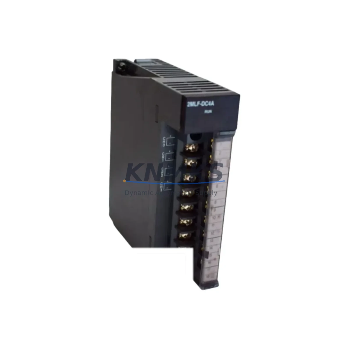
Honeywell 2MLF-DC4A Migration-Ready Digital Input Module for Legacy Control Systems
The Honeywell 2MLF-DC4A is a 24 VDC, 16-channel digital input module engineered for the Honeywell Modular I/O (MIO) platform. As legacy DCS and PLC installations age beyond their supported lifecycle, the 2MLF-DC4A has become a critical migration-ready component for engineers tasked with upgrading aging control cabinets, replacing discontinued field I/O modules, and restoring system integrity without full-platform replacement. Whether you are executing a phased retrofit of a Honeywell TDC 3000, Experion PKS, or a third-party PLC rack that previously interfaced with Honeywell I/O subsystems, the 2MLF-DC4A provides a verified drop-in path that minimizes engineering rework and field downtime.
Before committing to a replacement, engineers must confirm several critical parameters: the 24 VDC sourcing or sinking configuration of the existing field wiring, the terminal block pinout on the existing I/O carrier or base, the backplane slot addressing scheme used by the legacy controller, and whether the existing PLC program references the module by slot number or by I/O tag. In Honeywell Modular I/O architectures, the 2MLF-DC4A occupies a standard MIO slot and communicates over the internal backplane bus — no additional communication module is required for local rack configurations. For remote I/O drops connected via Honeywell’s FTA (Field Termination Assembly) infrastructure, verify that the FTA wiring harness and terminal assignments are compatible before powering the replacement module.
Migration Compatibility Table
| Parameter | Specification / Recommendation |
|---|---|
| Module Type | 16-Channel Digital Input, 24 VDC |
| Platform Compatibility | Honeywell Modular I/O (MIO) — TDC 3000, Experion PKS, HS series racks |
| Backplane Interface | Standard MIO backplane slot; no adapter required for same-generation racks |
| Terminal / Wiring | Verify FTA or I/O carrier pinout before installation; sourcing/sinking polarity must match field devices |
| Communication Protocol | Internal backplane bus; remote drops via Honeywell FTA infrastructure |
| Slot Addressing | Confirm slot number and I/O tag mapping in existing controller program before hot-swap |
| Firmware Compatibility | Verify controller firmware revision supports 2MLF-DC4A module descriptor; update if required |
| Physical Dimensions | Standard MIO module form factor; confirm rack slot clearance and adjacent module spacing |
| Replacement Path | Direct replacement for same-series MIO digital input modules; cross-reference legacy part numbers before ordering |
| Commissioning | Force I/O test recommended post-installation; verify all 16 channels in controller diagnostic display |
| Support terms | support terms confirmed by quotation — all units tested prior to shipment |
Retrofit Planning for Existing Automation Systems
A successful retrofit using the 2MLF-DC4A begins well before the module arrives on site. Start by auditing the existing I/O rack layout: identify the carrier or base card that the legacy digital input module is seated on, and confirm that the 2MLF-DC4A shares the same mechanical keying and backplane connector. In many Honeywell MIO installations, the I/O carrier (such as the MC-TAIH02 or equivalent FTA) remains in place during a module swap, which eliminates the need to re-terminate field wiring — a significant time saving during a planned maintenance window.
Power budget verification is equally important. The 2MLF-DC4A draws its operating power from the rack’s internal 24 VDC bus. Before inserting the replacement module, confirm that the rack power supply — often a Honeywell MC-PDPY22 or equivalent redundant power module — has sufficient headroom to support the new module alongside all other populated slots. If the rack is near its power budget limit, consider redistributing I/O loads across multiple racks or upgrading the power supply before proceeding.
For installations where the 2MLF-DC4A is being introduced into a mixed-vendor environment — for example, a control cabinet that also houses a Siemens ET 200M remote I/O drop or an Allen-Bradley 1756 ControlLogix chassis — pay close attention to the communication gateway or protocol converter that bridges the Honeywell I/O subsystem to the host controller. Devices such as Honeywell’s HC900 communication module or a third-party Modbus/PROFIBUS gateway must be configured to recognize the new module’s channel count and data format. Confirm that the HMI screens — whether running on Honeywell’s Station or a third-party SCADA platform — correctly map the 16 digital input channels to the appropriate process displays and alarm groups.
Signal isolation is another consideration in legacy retrofit projects. If the existing installation uses signal isolators or barriers between the field devices and the I/O module terminals, verify that the isolator output voltage and current ratings are compatible with the 2MLF-DC4A’s input threshold specifications. In high-noise industrial environments, adding a DIN-rail mounted signal isolator — such as a Phoenix Contact or Weidmuller barrier strip — between the field wiring and the module terminals can improve signal integrity and reduce nuisance trips during commissioning. Additionally, if the retrofit involves extending the I/O count beyond the original rack capacity, a Honeywell MIO expansion rack with a dedicated backplane extender cable may be required to accommodate additional 2MLF-DC4A modules or complementary digital output modules.
Downtime Control During System Migration
Minimizing unplanned downtime is the primary concern in any live-plant I/O module replacement. For the 2MLF-DC4A, the recommended approach is a pre-staged swap: configure and bench-test the replacement module in a lab environment before the scheduled maintenance window, using a spare MIO rack or a portable test fixture to verify all 16 input channels respond correctly to 24 VDC signals. Document the existing module’s slot address, I/O tag assignments, and any custom channel masking or filtering parameters configured in the controller before removal.
During the swap window, export a backup of the controller program and I/O configuration database before touching any hardware. This protects the original program logic and allows a rapid rollback if the replacement module introduces unexpected behavior. After seating the 2MLF-DC4A, power up the rack and observe the module’s status LEDs: a solid green RUN indicator confirms successful backplane communication. Use the controller’s online diagnostic tools to force-read all 16 input channels and compare the results against the pre-swap baseline. If any channel shows an unexpected state, check the field wiring continuity and the FTA terminal connections before assuming a module fault.
For critical process loops where even a brief I/O interruption is unacceptable, consider implementing a temporary hardwired bypass on the affected input channels during the swap — routing the field signals through a portable relay panel that feeds a parallel input to the controller via a spare I/O slot. This approach maintains control continuity throughout the physical module exchange and is particularly valuable in applications such as burner management, compressor protection, or safety interlock systems where a loss of input signal could trigger an unplanned shutdown. Once the 2MLF-DC4A is confirmed operational, remove the bypass and restore normal field wiring, then perform a final channel-by-channel verification before releasing the system back to operations.
Retrofit Support FAQ
Q1: Is the 2MLF-DC4A a direct drop-in replacement for other Honeywell MIO digital input modules?
The 2MLF-DC4A is designed for the Honeywell Modular I/O platform and shares the standard MIO mechanical and backplane interface. However, direct interchangeability depends on the specific legacy part number being replaced. Always cross-reference the original module’s channel count, voltage rating, and carrier compatibility before ordering. Our team can assist with cross-reference verification prior to shipment.
Q2: What commissioning steps are required after installing the 2MLF-DC4A?
After physical installation, confirm backplane communication via the controller’s module status display, then perform a forced I/O test on all 16 channels. Verify that the HMI displays and alarm groups correctly reflect the new module’s channel data. If the controller requires a firmware update to recognize the 2MLF-DC4A module descriptor, apply the update during the maintenance window before returning the system to service.
Q3: Can the 2MLF-DC4A be used in a system that also includes Honeywell analog input modules and communication modules?
Yes. The 2MLF-DC4A coexists with other MIO-compatible modules in the same rack, including analog input modules, digital output modules, and communication interface modules. Ensure the rack power supply budget accounts for all populated modules, and verify that the controller’s I/O configuration database is updated to reflect the new module type in the affected slot.
Q4: What support terms and pre-shipment testing does KNMKS provide for the 2MLF-DC4A?
All 2MLF-DC4A units supplied by KNMKS are tested prior to shipment to verify backplane communication, channel integrity, and LED status indication. Each unit carries a support terms confirmed by quotation covering manufacturing defects and functional failures under normal operating conditions. In-stock units are available for immediate dispatch to support urgent replacement and unplanned outage recovery scenarios.
© 2026 KNMKS. All rights reserved.
Original Source: https://knmks.com
Contact: admin@knmks.com | +86 18359268345
Product Identification
- Brand / Ecosystem
-
Honeywell
Honeywell - Model / Series
- 2MLF-DC4A
- Product Family
- PLCs & Controllers
- Availability Status
- Available on request after model and quantity confirmation
- Inquiry Type
- B2B RFQ, replacement inquiry and project spare-part request
- Pre-Quote Check
- Exact SKU, brand, series, quantity, nameplate photos and destination country are checked before quotation
System Path
Where this product fits in the KNMKS automation structure.
Specification & Inquiry Focus
- Control platform
- PLC, PAC and modular controllers
- Common needs
- CPU, rack, power and I/O expansion
- Project support
- Replacement, cabinet build and maintenance
Buyer Confirmation
Information KNMKS checks before replying.
- Exact model
- 2MLF-DC4A
- Brand / ecosystem
- Honeywell
- Product family
- PLCs & Controllers
- Application note
- Replacement, maintenance, project build or spare-part list
- Useful photos
- Nameplate, installed unit, cabinet layout or connector side
- Delivery details
- Quantity, destination country and target schedule
Document Support
Files and notes can be confirmed during quotation.
- Product photos or nameplate confirmation when available
- Packing and delivery notes before quotation confirmation
- Support scope and delivery terms confirmed per inquiry
- Export document coordination for qualified B2B requests
Inquiry Support
- Model cross-checking before quotation
- CPU, power, rack and expansion module matching
- Support for replacement and project inquiry
What to Send Us
- Brand and exact model number: Honeywell 2MLF-DC4A
- Quantity and required delivery time
- Application, replacement requirement or nameplate photo
- Destination country and shipping preference
RFQ Preparation
This is a product inquiry page built for RFQ communication.
Fast Model Check
Send this model to KNMKS for confirmation.
Include quantity, destination country and photos if this is a maintenance replacement. The inquiry will be saved with a reference number after submission.
Brand & Compatibility Note
KNMKS displays automation product information for well-known industrial brand ecosystems and compatible replacement references. Brand names are used for product identification and compatibility reference only; final availability and commercial terms are confirmed per quotation.
 Manufacturing
 Machine Tools
 Packaging
 Energy & Power
 HMI & Displays
 Servo Systems
 Variable Frequency Drives
 Sensors