
Overview
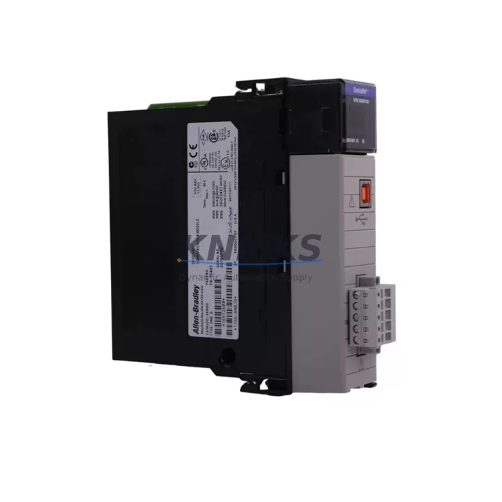
Allen-Bradley 1756-DNB Migration-Ready DeviceNet Scanner for Legacy Control Systems
The Allen-Bradley 1756-DNB is a DeviceNet Scanner Module designed for the ControlLogix 1756 backplane platform. As legacy DeviceNet networks age and original hardware reaches end-of-life, the 1756-DNB remains a critical component for facilities that must maintain DeviceNet communication integrity without undertaking a full platform migration. This module enables engineers to sustain existing DeviceNet topologies — including multi-drop trunk lines, T-port taps, and sealed connector networks — while upgrading surrounding infrastructure such as the 1756-L7x or 1756-L8x ControlLogix controllers, 1756-EN2T EtherNet/IP bridge modules, and 1756-PA75 or 1756-PB75 power supplies.
For plants running legacy 1756-DNB units that are no longer available through standard distribution channels, this stock unit provides a verified drop-in replacement path. Before installation, engineers should confirm backplane slot assignment, module address configuration in RSLogix 5000 or Studio 5000, and the DeviceNet network baud rate (125K, 250K, or 500K). The existing I/O tree and explicit messaging connections mapped to the original scanner must be validated against the replacement unit’s node address and scanlist configuration to avoid communication faults on startup.
Migration Compatibility Table
| Parameter | Detail |
|---|---|
| Module SKU | 1756-DNB |
| Platform | Allen-Bradley ControlLogix 1756 |
| Network Protocol | DeviceNet (CAN-based, IEC 62026-3) |
| Backplane Interface | 1756 ControlLogix backplane (direct slot mount) |
| Supported Baud Rates | 125 Kbps, 250 Kbps, 500 Kbps |
| Max DeviceNet Nodes | 64 nodes (node 0–63) |
| I/O Data Capacity | Up to 124 bytes input / 124 bytes output |
| Terminal / Connector | 5-pin open-style DeviceNet connector (V+, CAN_H, Shield, CAN_L, V−) |
| Power Requirement | Backplane powered; DeviceNet network requires external 24 VDC supply |
| Compatible Controllers | 1756-L6x, 1756-L7x, 1756-L8x ControlLogix families |
| Programming Software | RSLogix 5000 / Studio 5000 Logix Designer |
| Firmware Compatibility | Verify firmware revision against Studio 5000 project revision before swap |
| Replacement Recommendation | Direct slot replacement; re-import scanlist and verify node addresses post-installation |
| Commissioning Focus | Node address, baud rate, scanlist rebuild, I/O mapping verification, explicit message paths |
| Support terms | support terms confirmed by quotation — functional test report available on request |
Retrofit Planning for Existing Automation Systems
Retrofitting a DeviceNet network anchored by the 1756-DNB requires a structured approach that accounts for both the scanner module itself and the surrounding control architecture. In a typical ControlLogix chassis, the 1756-DNB occupies a dedicated backplane slot alongside the 1756-L7x controller, one or more 1756-EN2T EtherNet/IP communication modules, and a 1756-IB16 or 1756-OB16E digital I/O module. When replacing the scanner, the chassis layout must be preserved to avoid slot-address conflicts that would require program modifications in Studio 5000.
On the DeviceNet network side, field devices such as PowerFlex 40 or PowerFlex 70 variable frequency drives, 1769-SDN CompactLogix DeviceNet scanners used in satellite panels, and ArmorBlock I/O nodes are typically mapped in the 1756-DNB scanlist. Each of these devices must retain its original node address and I/O size allocation. Any change to the scanlist — even a temporary removal and re-add — will require re-verification of the associated ladder logic or function block routines that reference the I/O tags produced by the scanner.
For facilities also upgrading their HMI layer, FactoryTalk View SE or ME screens that display DeviceNet device status tags sourced from the 1756-DNB must be reviewed. Tag paths referencing the scanner’s produced data arrays should be confirmed against the replacement module’s tag structure before the HMI is brought back online. If the control cabinet also houses a 1756-DHRIO Data Highway Plus / Remote I/O bridge module for legacy SLC or PLC-5 integration, the migration window should be coordinated to avoid simultaneous communication disruptions across both networks.
Downtime Control During System Migration
Minimizing unplanned downtime during a 1756-DNB replacement begins with pre-migration preparation completed entirely offline. Before the maintenance window opens, the existing Studio 5000 project file should be exported and archived, including the full DeviceNet scanlist configuration accessible through the module’s properties in the I/O tree. A screenshot or export of the scanlist — capturing each node address, input/output sizes, and electronic key settings — serves as the reference document for post-swap verification.
During the physical swap, the DeviceNet trunk cable should be disconnected at the scanner’s 5-pin connector before the module is removed from the backplane. The replacement 1756-DNB should be inserted into the same slot, powered up, and allowed to complete its self-test sequence before the DeviceNet cable is reconnected. Once the network is live, the module’s LED indicators (MS and NS) should confirm normal operation before the controller is switched from Program to Run mode.
To protect original program logic, the controller should remain in Program mode throughout the hardware swap. This prevents the PLC from executing output commands against a partially initialized DeviceNet network. After the scanlist is confirmed and all node devices report healthy status in RSLinx Classic or Studio 5000’s online diagnostics, the controller can be returned to Run mode. A controlled, phased restart — beginning with non-critical DeviceNet nodes and progressing to drive and actuator nodes — further reduces the risk of process upsets during the commissioning phase.
Retrofit Support FAQ
Q1: Is the 1756-DNB a direct replacement for an existing 1756-DNB in the same chassis slot?
Yes. The 1756-DNB is a slot-for-slot replacement within any ControlLogix 1756 chassis. No backplane wiring changes are required. After installation, the DeviceNet scanlist must be re-imported or manually rebuilt in Studio 5000, and node addresses must be verified to match the original configuration.
Q2: What commissioning steps are required after swapping the module?
After physical installation, connect the DeviceNet cable, power the network, and open the module properties in Studio 5000 online. Rebuild or import the scanlist, verify each node’s I/O size and address, confirm the network baud rate matches all field devices, and check the MS/NS LED status. Run a full I/O force test on non-critical outputs before returning the system to automatic operation.
Q3: How is the unit tested before shipment?
Each 1756-DNB unit undergoes a functional power-on test and backplane communication verification prior to shipment. A test report is available on request. Units are shipped in anti-static packaging with original-style labeling. The support terms confirmed by quotation cover functional failure under normal operating conditions.
Q4: What is the stock availability and lead time?
Units are available from current inventory. Standard orders ship within 1–3 business days. For urgent replacement requirements or multi-unit orders, contact the sales team directly to confirm allocation and expedited dispatch options.
© 2026 KNMKS. All rights reserved.
Original Source: https://knmks.com
Contact: admin@knmks.com | +86 18359268345
Product Identification
- Brand / Ecosystem
-
Allen-Bradley
Allen-Bradley - Model / Series
-
1756-DNB
ControlLogix Series - Product Family
- PLCs & Controllers
- Availability Status
- Available on request after model and quantity confirmation
- Inquiry Type
- B2B RFQ, replacement inquiry and project spare-part request
- Pre-Quote Check
- Exact SKU, brand, series, quantity, nameplate photos and destination country are checked before quotation
System Path
Where this product fits in the KNMKS automation structure.
Specification & Inquiry Focus
- Control platform
- PLC, PAC and modular controllers
- Common needs
- CPU, rack, power and I/O expansion
- Project support
- Replacement, cabinet build and maintenance
Buyer Confirmation
Information KNMKS checks before replying.
- Exact model
- 1756-DNB
- Brand / ecosystem
- Allen-Bradley
- Product family
- PLCs & Controllers
- Application note
- Replacement, maintenance, project build or spare-part list
- Useful photos
- Nameplate, installed unit, cabinet layout or connector side
- Delivery details
- Quantity, destination country and target schedule
Document Support
Files and notes can be confirmed during quotation.
- Product photos or nameplate confirmation when available
- Packing and delivery notes before quotation confirmation
- Support scope and delivery terms confirmed per inquiry
- Export document coordination for qualified B2B requests
Inquiry Support
- Model cross-checking before quotation
- CPU, power, rack and expansion module matching
- Support for replacement and project inquiry
What to Send Us
- Brand and exact model number: Allen-Bradley 1756-DNB
- Quantity and required delivery time
- Application, replacement requirement or nameplate photo
- Destination country and shipping preference
RFQ Preparation
This is a product inquiry page built for RFQ communication.
Fast Model Check
Send this model to KNMKS for confirmation.
Include quantity, destination country and photos if this is a maintenance replacement. The inquiry will be saved with a reference number after submission.
Brand & Compatibility Note
KNMKS displays automation product information for well-known industrial brand ecosystems and compatible replacement references. Brand names are used for product identification and compatibility reference only; final availability and commercial terms are confirmed per quotation.
 Manufacturing
 Machine Tools
 Packaging
 Energy & Power
 HMI & Displays
 Servo Systems
 Variable Frequency Drives
 Sensors