
Overview
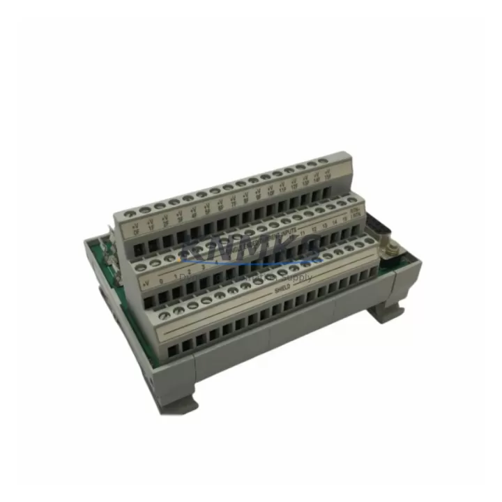
Allen-Bradley 1492-AIFM16-F-3 Migration-Ready Analog IFM for Legacy Control Systems
The Allen-Bradley 1492-AIFM16-F-3 is a 16-channel analog interface module (IFM) engineered for seamless integration into existing Rockwell Automation control architectures. As legacy analog I/O wiring systems reach end-of-life or become increasingly difficult to source, the 1492-AIFM16-F-3 serves as a direct migration-ready replacement that preserves existing field wiring while enabling compatibility with modern 1756 ControlLogix and 1769 CompactLogix analog I/O modules. For facilities managing aging control panels, this module eliminates the need for full cabinet rewiring during system modernization projects.
Designed to interface with Rockwell’s 1492-AIFM series wiring system, the 1492-AIFM16-F-3 supports 3-wire field device connections across all 16 channels, making it particularly well-suited for replacing discontinued IFM variants in temperature, pressure, and flow measurement loops. Engineers undertaking retrofit projects should verify terminal block pitch compatibility, confirm the analog module slot assignment within the existing 1756 or 1769 chassis, and validate that the replacement module’s channel-to-terminal mapping aligns with the original program tag structure before going live.
When planning a migration involving the 1492-AIFM16-F-3, the power budget of the existing I/O chassis must be reviewed. The 1756-PA75 or 1756-PB75 power supply modules commonly found in ControlLogix racks should be assessed to confirm sufficient current capacity for the updated I/O configuration. If the existing rack is near its power limit, adding a 1756-A17 or 1756-A13 expansion chassis with a dedicated power supply may be required before the IFM replacement can proceed safely.
For systems originally built around the 1492-AIFM8-F-3 or other 8-channel IFM variants, upgrading to the 16-channel 1492-AIFM16-F-3 can consolidate wiring density and reduce the number of terminal assemblies in the control cabinet. This is especially valuable in retrofit scenarios where cabinet space is constrained and the customer needs to expand analog I/O capacity without adding a new enclosure. Confirm available DIN rail space and verify that the cable management channels can accommodate the additional field wiring before finalizing the retrofit design.
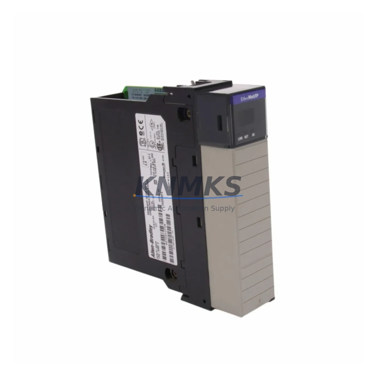
Communication integrity is a critical concern during any IFM migration. The 1492-AIFM16-F-3 connects to the analog I/O module via a pre-wired cable assembly, and the integrity of this cable — including connector seating and cable routing away from high-voltage conductors — must be verified during commissioning. In systems where the analog data feeds into a 1756-EN2T EtherNet/IP communication module for SCADA or DCS integration, the engineer should confirm that the analog module’s channel scaling parameters in Studio 5000 Logix Designer match the original program logic to avoid process variable offset errors after the swap.
HMI screen validation is another step that is frequently overlooked during IFM replacements. If the plant uses a PanelView Plus 7 or similar HMI terminal displaying analog process values sourced from the replaced module, each affected tag should be verified against the live process signal after the new IFM is installed and the program is downloaded. Any discrepancy in engineering unit scaling or alarm setpoints should be corrected before returning the system to automatic control.
Firmware compatibility between the analog I/O module and the ControlLogix controller should also be confirmed. Rockwell Automation periodically releases firmware updates that affect analog module behavior, and a mismatch between the controller firmware and the I/O module firmware can result in inhibited module faults. Reviewing the Product Compatibility and Download Center (PCDC) for the specific firmware revision of the 1756-IF16 or 1769-IF16C analog module paired with this IFM is recommended before the cutover.
For customers managing spare parts lifecycle programs, the 1492-AIFM16-F-3 is stocked and available for immediate shipment. Maintaining a buffer stock of IFM modules alongside critical analog I/O cards such as the 1756-IF16 reduces the risk of extended downtime caused by obsolete wiring accessories. Our inventory is tested prior to shipment, and each unit is covered by a support terms confirmed by quotation from the date of delivery.
Migration Compatibility Table
| Parameter | Details |
|---|---|
| SKU / Part Number | 1492-AIFM16-F-3 |
| Brand / Series | Allen-Bradley / 1492-AIFM Series |
| Channels | 16-channel analog interface |
| Wiring Type | 3-wire field device connection per channel |
| Compatible I/O Modules | 1756-IF16, 1769-IF16C, 1769-IF8 (via adapter) |
| Compatible Platforms | 1756 ControlLogix, 1769 CompactLogix |
| Replaces / Supersedes | 1492-AIFM8-F-3, discontinued 1492-AIFM variants |
| Installation Interface | DIN rail mount; pre-wired cable assembly to I/O module |
| Communication Compatibility | EtherNet/IP via paired ControlLogix / CompactLogix controller |
| Retrofit Recommendation | Direct drop-in for same-series IFM; verify terminal mapping and cable assembly part number |
| Commissioning Focus | Channel scaling, tag mapping, HMI value verification, firmware revision check |
| Support terms | support terms confirmed by quotation from date of shipment |
Retrofit Planning for Existing Automation Systems
A successful retrofit using the 1492-AIFM16-F-3 begins with a thorough audit of the existing control cabinet. Engineers should document the current IFM part number, the cable assembly connecting the IFM to the analog I/O module, and the terminal block wiring layout before any hardware is removed. In many legacy installations, the original cable assembly — such as the 1492-CABLE016Z — may also need to be replaced if it shows signs of insulation degradation or connector wear. Ordering the replacement cable assembly alongside the 1492-AIFM16-F-3 avoids a second maintenance window.
The 1756-IF16 analog input module, commonly paired with this IFM in ControlLogix systems, should be inspected for firmware currency as part of the retrofit plan. If the system also includes a 1756-OF8 analog output module sharing the same chassis, its wiring and scaling configuration should be documented to ensure the retrofit does not inadvertently affect output channel behavior. For CompactLogix-based systems, the 1769-IF16C is the typical paired module, and its slot address within the local I/O bus must be confirmed in the Studio 5000 project file before the new IFM is connected.
In control cabinets where a 1756-EN2T or 1756-EN2TR EtherNet/IP bridge module provides remote I/O connectivity, the engineer should verify that the analog module’s connection path in the controller project is correctly mapped and that no IP address conflicts exist on the plant network segment. Signal isolators — such as those used to condition 4–20 mA loops from field transmitters before they reach the IFM terminals — should also be tested for output accuracy after the IFM swap to rule out any signal conditioning drift that could be misattributed to the new module.
Downtime Control During System Migration
Minimizing production downtime during an IFM replacement requires careful pre-staging and a clearly defined cutover sequence. Before the maintenance window begins, the replacement 1492-AIFM16-F-3 should be pre-labeled with channel identifiers matching the existing field wiring schedule. The Studio 5000 program should be backed up and the current controller firmware version recorded. If the system supports partial rack redundancy or has a hot-standby controller configuration using a 1756-RM2 redundancy module, the cutover can be planned to occur during a controller switchover, further reducing the impact on the process.
During the physical swap, field wiring should be transferred one terminal at a time using the documented wiring schedule, with each channel verified against the original drawing before the next is moved. After all field wiring is transferred and the new cable assembly is connected to the analog I/O module, the controller should be placed in Program mode before the module is re-enabled to prevent spurious output commands. Once the module is online and all channels are reading correctly in the controller tag database, the HMI displays should be checked for correct process variable representation before returning the controller to Run mode.
Post-cutover, a 30-minute observation period is recommended to confirm signal stability across all 16 channels before the maintenance window is formally closed. Any channel showing unexpected behavior should be investigated at the field device level — checking transmitter loop power, wiring continuity, and signal isolator output — before concluding that the IFM module itself is at fault. This structured approach protects the original program logic, maintains field control continuity, and significantly reduces the risk of a repeat maintenance event.
Retrofit Support FAQ
Q: Is the 1492-AIFM16-F-3 a direct replacement for the 1492-AIFM8-F-3?
A: The 1492-AIFM16-F-3 is a 16-channel module while the 1492-AIFM8-F-3 is an 8-channel variant. They are not pin-for-pin interchangeable, but the 16-channel version can replace the 8-channel in applications where additional I/O capacity is needed and the paired analog I/O module supports 16 channels. Verify the cable assembly part number and the I/O module channel count before ordering.
Q: What pre-shipment testing is performed on the 1492-AIFM16-F-3?
A: Each unit undergoes functional inspection and continuity testing across all terminal connections prior to shipment. Units are verified against the original Allen-Bradley specification for terminal block integrity and connector fit. A support terms confirmed by quotation is included from the date of shipment.
Q: How do I confirm firmware compatibility between the paired analog module and my ControlLogix controller?
A: Use Rockwell Automation’s Product Compatibility and Download Center (PCDC) to cross-reference the firmware revision of your 1756 or 1769 controller with the supported firmware for the paired analog I/O module. Mismatched firmware can cause module inhibit faults. Update the controller or module firmware during the planned maintenance window before the IFM swap if a mismatch is identified.
Q: What is the typical lead time and stock availability for the 1492-AIFM16-F-3?
A: We maintain ready stock of the 1492-AIFM16-F-3 for immediate shipment. Standard orders are processed and dispatched within 1–3 business days. For urgent retrofit projects or bulk orders, contact our sales team directly to confirm current inventory levels and expedited shipping options.
© 2026 KNMKS. All rights reserved.
Original Source: https://knmks.com
Contact: admin@knmks.com | +86 18359268345
Product Identification
- Brand / Ecosystem
-
Allen-Bradley
Allen-Bradley - Model / Series
-
1492-AIFM16-F-3
ControlLogix Series - Product Family
- PLCs & Controllers
- Availability Status
- Available on request after model and quantity confirmation
- Inquiry Type
- B2B RFQ, replacement inquiry and project spare-part request
- Pre-Quote Check
- Exact SKU, brand, series, quantity, nameplate photos and destination country are checked before quotation
System Path
Where this product fits in the KNMKS automation structure.
Specification & Inquiry Focus
- Control platform
- PLC, PAC and modular controllers
- Common needs
- CPU, rack, power and I/O expansion
- Project support
- Replacement, cabinet build and maintenance
Buyer Confirmation
Information KNMKS checks before replying.
- Exact model
- 1492-AIFM16-F-3
- Brand / ecosystem
- Allen-Bradley
- Product family
- PLCs & Controllers
- Application note
- Replacement, maintenance, project build or spare-part list
- Useful photos
- Nameplate, installed unit, cabinet layout or connector side
- Delivery details
- Quantity, destination country and target schedule
Document Support
Files and notes can be confirmed during quotation.
- Product photos or nameplate confirmation when available
- Packing and delivery notes before quotation confirmation
- Support scope and delivery terms confirmed per inquiry
- Export document coordination for qualified B2B requests
Inquiry Support
- Model cross-checking before quotation
- CPU, power, rack and expansion module matching
- Support for replacement and project inquiry
What to Send Us
- Brand and exact model number: Allen-Bradley 1492-AIFM16-F-3
- Quantity and required delivery time
- Application, replacement requirement or nameplate photo
- Destination country and shipping preference
RFQ Preparation
This is a product inquiry page built for RFQ communication.
Fast Model Check
Send this model to KNMKS for confirmation.
Include quantity, destination country and photos if this is a maintenance replacement. The inquiry will be saved with a reference number after submission.
Brand & Compatibility Note
KNMKS displays automation product information for well-known industrial brand ecosystems and compatible replacement references. Brand names are used for product identification and compatibility reference only; final availability and commercial terms are confirmed per quotation.
 Manufacturing
 Machine Tools
 Packaging
 Energy & Power
 HMI & Displays
 Servo Systems
 Variable Frequency Drives
 Sensors