
Overview
Allen-Bradley 1756-DMA31 Migration-Ready SynchLink Module: Legacy System Migration and Compatible Upgrade
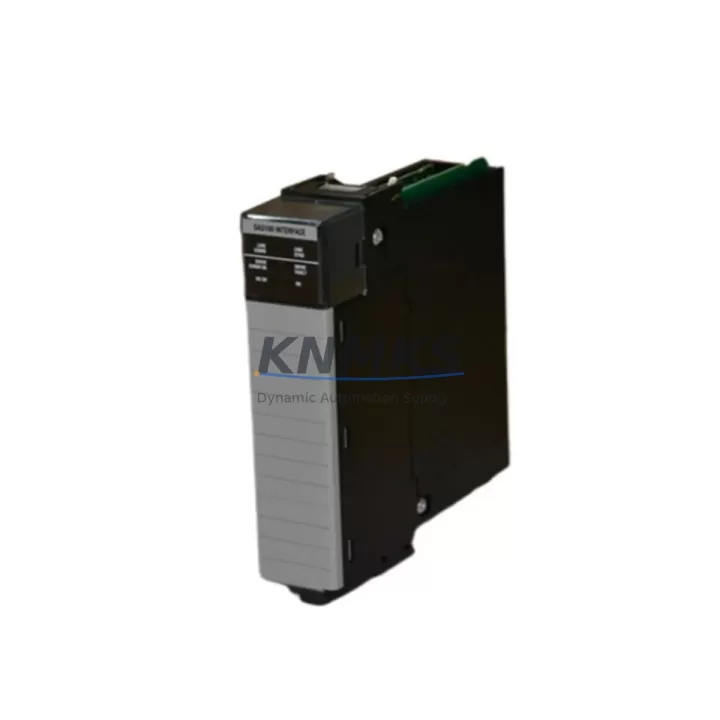
The Allen-Bradley 1756-DMA31 is a SynchLink Drive Interface Module designed for the ControlLogix 1756 platform, providing high-speed synchronization between ControlLogix controllers and compatible PowerFlex drive systems. As legacy automation infrastructure ages and OEM support for discontinued modules becomes increasingly limited, the 1756-DMA31 remains a critical component for facilities managing coordinated multi-axis drive systems, winder applications, and high-performance motion control architectures built on the ControlLogix backplane.
For engineers undertaking control system modernization projects, the 1756-DMA31 serves as both a direct replacement for failed or end-of-life units and as a validated retrofit component within existing 1756 chassis configurations. Its role in SynchLink fiber-optic communication networks — connecting the ControlLogix controller to PowerFlex 700S and PowerFlex 700H drives — makes it indispensable in applications where drive synchronization, torque coordination, and velocity reference distribution must be preserved without a full system redesign.
Migration Compatibility Table
| Parameter | Details |
|---|---|
| Module SKU | 1756-DMA31 |
| Series / Platform | Allen-Bradley ControlLogix 1756 |
| Communication Interface | SynchLink (fiber-optic, point-to-point or ring topology) |
| Backplane Interface | ControlLogix 1756 backplane (compatible with 1756-A4, 1756-A7, 1756-A10, 1756-A13, 1756-A17 chassis) |
| Compatible Drives | PowerFlex 700S (Series A/B), PowerFlex 700H |
| Replacement Candidates | 1756-DMA31 (same SKU, direct swap); legacy SynchLink configurations previously using 1756-DMxx variants |
| Installation Requirement | Single slot in 1756 chassis; fiber-optic ST connectors (TX/RX); no external power wiring required |
| Firmware Compatibility | Verify RSLogix 5000 / Studio 5000 project firmware revision matches controller series before installation |
| Programming Tool | RSLogix 5000 / Studio 5000 Logix Designer |
| Retrofit Recommendation | Direct slot replacement; re-download drive configuration via DriveExecutive or Connected Components Workbench after swap |
| Commissioning Focus | SynchLink node address, fiber-optic continuity check, drive parameter re-verification, motion task re-validation |
| Support terms | support terms confirmed by quotation — covers functional defects under normal operating conditions |
Retrofit Planning for Existing Automation Systems
Replacing the 1756-DMA31 within an operational ControlLogix system requires a structured approach that accounts for the interdependencies between the SynchLink network, the ControlLogix controller, and the connected drive infrastructure. Before initiating a swap, engineers should audit the existing 1756 chassis slot assignment to confirm the module occupies the correct position as defined in the RSLogix 5000 or Studio 5000 project file. Slot mismatches will prevent the controller from recognizing the module and may trigger faulted I/O tree entries that halt production.
Power budget verification is an essential pre-replacement step. The 1756-DMA31 draws power from the ControlLogix backplane via the installed 1756-Pxx power supply — typically a 1756-PA72 or 1756-PB72. Confirm that the chassis power supply has sufficient remaining capacity after accounting for all installed modules, including any 1756-EN2T EtherNet/IP communication modules, 1756-IB16 or 1756-OB16 digital I/O modules, and any 1756-L7x or 1756-L8x ControlLogix controllers occupying the same chassis. Overloaded power supplies are a common root cause of intermittent module faults in aging control cabinets.
The SynchLink fiber-optic cabling connecting the 1756-DMA31 to the PowerFlex 700S or PowerFlex 700H drives must be inspected for bend radius violations, connector contamination, and optical loss before the new module is installed. ST-type fiber connectors should be cleaned with appropriate optical cleaning tools. After physical installation, use the drive’s built-in diagnostic LEDs and the SynchLink status indicators on the 1756-DMA31 faceplate to confirm link establishment before re-enabling the motion task in the controller.
For facilities running coordinated multi-drive winder or draw systems, the SynchLink ring topology must be re-validated after any module replacement. Each node in the ring — including intermediate PowerFlex 700S drives acting as SynchLink pass-through nodes — must be confirmed online before the master controller resumes synchronization commands. If the existing project uses a 1756-M02AE or 1756-M08SE servo drive interface module in the same chassis for auxiliary axes, ensure that the motion group configuration in Studio 5000 correctly separates SynchLink-coordinated axes from servo-controlled axes to avoid cross-task timing conflicts.
Where the control cabinet also houses a 1756-ENBT or 1756-EN2T for remote I/O or HMI connectivity, verify that the EtherNet/IP network remains stable during the module swap. PanelView Plus HMI terminals connected via EtherNet/IP may display communication fault banners during the controller restart sequence; this is expected behavior and should be documented in the site’s maintenance procedure to avoid unnecessary operator intervention.
Downtime Control During System Migration
Minimizing unplanned downtime during a 1756-DMA31 replacement begins with pre-staging the replacement module and verifying its firmware revision against the existing project before the maintenance window opens. Export the current RSLogix 5000 or Studio 5000 project file and store a backup on a local engineering workstation — do not rely solely on the controller’s onboard memory for program recovery. If the controller supports partial import/export, isolate the SynchLink-related Add-On Instructions (AOIs) and motion task routines for targeted verification after the swap.
During the physical replacement, place the ControlLogix controller in Program mode rather than performing a hard power cycle where possible. This preserves the I/O connection state for non-SynchLink modules in the chassis and reduces the time required to re-establish EtherNet/IP connections to remote I/O adapters and HMI devices. After installing the 1756-DMA31, transition the controller to Run mode and monitor the SynchLink status bits in the controller tags before re-enabling the motion task.
For sites where continuous production cannot be interrupted, consider pre-configuring the replacement 1756-DMA31 offline using a spare ControlLogix chassis and a laptop running Studio 5000. Validate the module’s SynchLink node address and drive parameter download sequence in the offline environment before bringing the replacement unit to the production floor. This approach — combined with a documented step-by-step commissioning checklist — consistently reduces live commissioning time and lowers the risk of parameter entry errors under time pressure.
All units supplied are functionally tested prior to shipment. Each 1756-DMA31 is covered by a support terms confirmed by quotation against manufacturing defects and functional failures under normal operating conditions, providing confidence for both emergency replacements and planned retrofit projects.
Retrofit Support FAQ
Q: Is the 1756-DMA31 a direct drop-in replacement for a failed unit in my existing ControlLogix chassis?
A: Yes. The 1756-DMA31 is a single-slot ControlLogix module and installs directly into any open or same-position slot in a 1756 chassis. After physical installation, re-download the drive configuration to the connected PowerFlex 700S or 700H drives and verify SynchLink link status before returning the system to Run mode. No hardware wiring changes are required beyond reconnecting the fiber-optic ST cables.
Q: What commissioning steps are required after replacing the 1756-DMA31?
A: After installation, confirm the module’s slot address matches the RSLogix 5000 / Studio 5000 project configuration. Check SynchLink status LEDs on the module faceplate for link establishment. Re-download drive parameters via DriveExecutive or Connected Components Workbench if the replacement drive has been factory-reset. Validate motion task execution and SynchLink synchronization status bits in the controller tag database before resuming production.
Q: How do I verify compatibility with my existing firmware and software revision?
A: Open your Studio 5000 project and note the controller firmware revision and the module catalog number/revision listed in the I/O tree. Cross-reference with the 1756-DMA31 product compatibility matrix in the Rockwell Automation publication 1756-UM534. If the module revision does not match, a firmware update via ControlFLASH or ControlFLASH Plus may be required. Contact our technical team with your project firmware revision for pre-shipment compatibility confirmation.
Q: What support terms and testing does this unit include?
A: Every 1756-DMA31 supplied by KNMKS is functionally tested prior to shipment, including backplane communication verification and SynchLink port integrity checks. The unit is covered by a support terms confirmed by quotation from the date of shipment, covering functional defects under normal operating conditions. Expedited shipping options are available for emergency breakdown situations. Contact admin@knmks.com or +86 18359268345 for stock confirmation and lead time.
© 2026 KNMKS. All rights reserved.
Original Source: https://knmks.com
Contact: admin@knmks.com | +86 18359268345
Product Identification
- Brand / Ecosystem
-
Allen-Bradley
Allen-Bradley - Model / Series
-
1756-DMA31
ControlLogix Series - Product Family
- PLCs & Controllers
- Availability Status
- Available on request after model and quantity confirmation
- Inquiry Type
- B2B RFQ, replacement inquiry and project spare-part request
- Pre-Quote Check
- Exact SKU, brand, series, quantity, nameplate photos and destination country are checked before quotation
System Path
Where this product fits in the KNMKS automation structure.
Specification & Inquiry Focus
- Control platform
- PLC, PAC and modular controllers
- Common needs
- CPU, rack, power and I/O expansion
- Project support
- Replacement, cabinet build and maintenance
Buyer Confirmation
Information KNMKS checks before replying.
- Exact model
- 1756-DMA31
- Brand / ecosystem
- Allen-Bradley
- Product family
- PLCs & Controllers
- Application note
- Replacement, maintenance, project build or spare-part list
- Useful photos
- Nameplate, installed unit, cabinet layout or connector side
- Delivery details
- Quantity, destination country and target schedule
Document Support
Files and notes can be confirmed during quotation.
- Product photos or nameplate confirmation when available
- Packing and delivery notes before quotation confirmation
- Support scope and delivery terms confirmed per inquiry
- Export document coordination for qualified B2B requests
Inquiry Support
- Model cross-checking before quotation
- CPU, power, rack and expansion module matching
- Support for replacement and project inquiry
What to Send Us
- Brand and exact model number: Allen-Bradley 1756-DMA31
- Quantity and required delivery time
- Application, replacement requirement or nameplate photo
- Destination country and shipping preference
RFQ Preparation
This is a product inquiry page built for RFQ communication.
Fast Model Check
Send this model to KNMKS for confirmation.
Include quantity, destination country and photos if this is a maintenance replacement. The inquiry will be saved with a reference number after submission.
Brand & Compatibility Note
KNMKS displays automation product information for well-known industrial brand ecosystems and compatible replacement references. Brand names are used for product identification and compatibility reference only; final availability and commercial terms are confirmed per quotation.
 Manufacturing
 Machine Tools
 Packaging
 Energy & Power
 HMI & Displays
 Servo Systems
 Variable Frequency Drives
 Sensors