
Overview
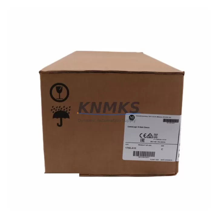
Allen-Bradley 1756-A10 Migration-Ready Chassis for Legacy ControlLogix Systems
The Allen-Bradley 1756-A10 is a 10-slot ControlLogix chassis designed for seamless integration into existing Rockwell Automation control architectures. As legacy PLC-5 and SLC 500 platforms approach end-of-life, the 1756-A10 serves as the structural backbone for migration projects that demand minimal downtime, verified backplane compatibility, and long-term spare parts availability. Whether you are upgrading a legacy control cabinet, expanding I/O capacity, or replacing a discontinued chassis in a running production line, the 1756-A10 provides the physical and electrical foundation required for a reliable retrofit.
Each unit is pre-tested prior to shipment, covered by a support terms confirmed by quotation, and stocked for immediate global dispatch. For procurement teams managing multi-site automation upgrades or MRO inventory replenishment, the 1756-A10 represents a standardized, migration-ready solution with a documented replacement path from older Rockwell platforms.
Migration Compatibility Table
| Parameter | 1756-A10 Specification | Migration Notes |
|---|---|---|
| Slot Count | 10 slots | Verify module count from legacy rack before ordering; upsize from 7-slot (1756-A7) if I/O expansion is required |
| Backplane Compatibility | ControlLogix 1756 backplane | Compatible with all 1756-series modules; not interchangeable with PLC-5 or SLC 500 racks |
| Power Supply Interface | Accepts 1756-PA72 / 1756-PB72 / 1756-PA75 / 1756-PB75 | Confirm AC or DC power supply variant before replacement; mismatch will prevent chassis power-up |
| Communication Modules | Supports 1756-EN2T, 1756-ENBT, 1756-CN2, 1756-DNB | Retain existing comm module addresses; re-slot in same position to preserve network node assignments |
| Controller Compatibility | All 1756-Lxx ControlLogix controllers | Firmware version on controller must match project file; upgrade firmware before re-commissioning |
| Installation Footprint | Standard DIN / panel mount | Verify cabinet depth and rail spacing; 1756-A10 requires adequate clearance for module insertion |
| Replacement Path | Direct drop-in for existing 1756-A10 installations | No program changes required if slot assignments are preserved |
| Support terms | 12 months | Covers manufacturing defects; includes pre-shipment functional test report on request |
Retrofit Planning for Existing Automation Systems
Successful integration of the 1756-A10 into a legacy control system requires a structured pre-migration audit. Begin by documenting the existing rack layout, including the slot positions of the 1756-L71 or 1756-L75 controller, any installed 1756-EN2T EtherNet/IP communication modules, and the I/O module assignments across analog and digital cards. Slot order directly affects the controller’s I/O tree in Studio 5000 Logix Designer; any deviation from the original layout will require a program update and re-download.
Power supply selection is a critical checkpoint. The 1756-A10 chassis accepts standard ControlLogix power supplies including the 1756-PA72 (120/240V AC) and 1756-PB72 (18–32V DC). Calculate the total backplane current draw from all installed modules before selecting the replacement supply. Overloading the backplane is a common cause of intermittent faults during post-retrofit commissioning.
For systems that include a 1756-DNB DeviceNet Bridge or a 1756-CN2 ControlNet module, preserve the original network node addresses during the chassis swap. DeviceNet and ControlNet topologies are node-sensitive; changing slot positions without updating the network configuration will result in communication faults that require scanner re-configuration and potential HMI screen remapping on connected PanelView terminals.
Where the legacy system includes a 1756-HIST2G HistorianE module or third-party data acquisition hardware, confirm that the new chassis backplane does not introduce timing conflicts with high-speed data logging tasks. In multi-chassis configurations connected via 1756-RM redundancy modules, the replacement chassis must match the firmware revision of the primary chassis to maintain redundancy synchronization.
Terminal wiring on field-side I/O modules does not change during a chassis swap, provided the same module types are reinstalled in identical slot positions. Use the original wiring diagrams and I/O module datasheets to verify terminal block compatibility before powering up the replacement chassis. Signal isolators installed upstream of analog input modules should be re-verified for loop power continuity after the chassis replacement is complete.
Downtime Control During System Migration
Minimizing production downtime during a chassis replacement requires advance preparation and a clearly defined cutover sequence. Before removing the legacy 1756-A10, export the controller project file from Studio 5000 and store a verified backup offline. Capture a screenshot or printed record of all module slot assignments, network node addresses, and I/O force statuses currently active in the system.
Where process continuity is critical, coordinate the chassis swap during a scheduled maintenance window. If the system supports partial redundancy via a 1756-RM module pair, initiate a controlled switchover to the secondary chassis before beginning work on the primary. This preserves control output continuity and protects the field devices from an uncontrolled power loss event.
During physical installation, seat each module firmly into the new chassis backplane before applying power. Loose module seating is a leading cause of backplane communication errors that are difficult to diagnose under time pressure. After power-up, verify the controller status LEDs, confirm EtherNet/IP node visibility on the network, and perform a controlled I/O force test on critical output channels before returning the system to automatic mode.
Post-commissioning, retain the replaced chassis for a minimum of 30 days as a standby spare. In facilities with long procurement lead times, maintaining a stocked 1756-A10 as a cold spare reduces the risk exposure from future unplanned failures. Our support terms confirmed by quotation and pre-shipment test protocol ensure that each unit dispatched is verified functional before it enters your spare parts inventory.
Retrofit Support FAQ
Q1: Is the 1756-A10 a direct replacement for my existing ControlLogix chassis without program changes?
Yes, provided you reinstall all modules in their original slot positions and use a compatible power supply. The controller will resume normal operation after power-up without requiring a program re-download, as long as the firmware version matches the stored project file.
Q2: What power supply variants are compatible with the 1756-A10?
The 1756-A10 is compatible with the 1756-PA72, 1756-PA75 (AC input) and 1756-PB72, 1756-PB75 (DC input) power supplies. Confirm your site power specification before ordering to avoid mismatch. Each power supply slots into the dedicated power supply bay on the left side of the chassis.
Q3: Does each unit undergo testing before shipment?
Yes. Every 1756-A10 unit is functionally tested prior to dispatch. A test report is available on request. Units are covered by a support terms confirmed by quotation against manufacturing defects from the date of shipment.
Q4: What is the typical lead time and do you maintain stock?
We maintain ready stock of the 1756-A10 for immediate global dispatch. Standard lead time is 3–7 business days depending on destination. For bulk procurement or project-based orders, contact our sales team to confirm allocation and arrange consolidated shipment.
© 2026 KNMKS. All rights reserved.
Original Source: https://knmks.com
Contact: admin@knmks.com | +86 18359268345
Product Identification
- Brand / Ecosystem
-
Allen-Bradley
Allen-Bradley - Model / Series
-
1756-A10
ControlLogix Series - Product Family
- PLCs & Controllers
- Availability Status
- Available on request after model and quantity confirmation
- Inquiry Type
- B2B RFQ, replacement inquiry and project spare-part request
- Pre-Quote Check
- Exact SKU, brand, series, quantity, nameplate photos and destination country are checked before quotation
System Path
Where this product fits in the KNMKS automation structure.
Specification & Inquiry Focus
- Control platform
- PLC, PAC and modular controllers
- Common needs
- CPU, rack, power and I/O expansion
- Project support
- Replacement, cabinet build and maintenance
Buyer Confirmation
Information KNMKS checks before replying.
- Exact model
- 1756-A10
- Brand / ecosystem
- Allen-Bradley
- Product family
- PLCs & Controllers
- Application note
- Replacement, maintenance, project build or spare-part list
- Useful photos
- Nameplate, installed unit, cabinet layout or connector side
- Delivery details
- Quantity, destination country and target schedule
Document Support
Files and notes can be confirmed during quotation.
- Product photos or nameplate confirmation when available
- Packing and delivery notes before quotation confirmation
- Support scope and delivery terms confirmed per inquiry
- Export document coordination for qualified B2B requests
Inquiry Support
- Model cross-checking before quotation
- CPU, power, rack and expansion module matching
- Support for replacement and project inquiry
What to Send Us
- Brand and exact model number: Allen-Bradley 1756-A10
- Quantity and required delivery time
- Application, replacement requirement or nameplate photo
- Destination country and shipping preference
RFQ Preparation
This is a product inquiry page built for RFQ communication.
Fast Model Check
Send this model to KNMKS for confirmation.
Include quantity, destination country and photos if this is a maintenance replacement. The inquiry will be saved with a reference number after submission.
Brand & Compatibility Note
KNMKS displays automation product information for well-known industrial brand ecosystems and compatible replacement references. Brand names are used for product identification and compatibility reference only; final availability and commercial terms are confirmed per quotation.
 Manufacturing
 Machine Tools
 Packaging
 Energy & Power
 HMI & Displays
 Servo Systems
 Variable Frequency Drives
 Sensors