
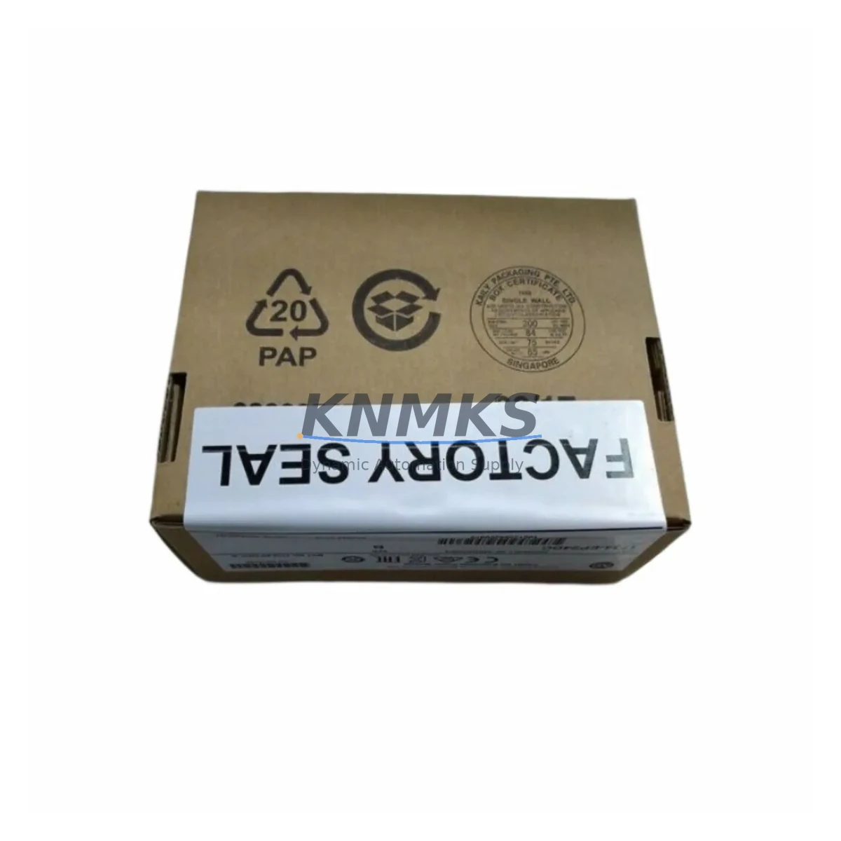
Overview
Allen-Bradley 1734-EP24DC Migration-Ready Power Supply for Legacy Control Systems
The Allen-Bradley 1734-EP24DC is a 24VDC expansion power supply module designed for the POINT I/O platform — one of Rockwell Automation’s most widely deployed distributed I/O architectures in legacy and active production environments. As aging control systems approach end-of-life and original spare parts become increasingly difficult to source, the 1734-EP24DC remains a critical component for engineers managing retrofit projects, panel upgrades, and system continuity across manufacturing, oil & gas, water treatment, and discrete automation facilities.
This module provides supplemental power to POINT I/O adapter segments where the base adapter’s power budget is insufficient to support the full complement of I/O modules. In retrofit scenarios, engineers frequently encounter situations where additional 1734-series digital or analog I/O modules — such as the 1734-IB8 8-point DC input module or the 1734-OB8 8-point DC output module — are added to an existing segment during a capacity expansion, pushing the segment beyond the original power budget. Inserting a 1734-EP24DC at the appropriate position in the terminal base assembly restores power balance without requiring a full rack redesign or adapter replacement.
When planning a migration or retrofit involving the 1734-EP24DC, engineers must verify several critical parameters before installation. Power capacity confirmation is the first step: calculate the total current draw of all downstream I/O modules on the segment and confirm the 1734-EP24DC’s 1.0A output at 24VDC is sufficient. Terminal wiring must be adapted to the existing field wiring scheme — the module uses standard POINT I/O terminal base wiring, but legacy installations may use older wire gauges or ferrule types that require re-termination. Backplane interface compatibility should be confirmed against the installed 1734-series adapter, whether a 1734-AENT EtherNet/IP adapter, a 1734-ADN DeviceNet adapter, or a 1734-APB PROFIBUS adapter, as the power supply module is protocol-agnostic but must be physically seated in a compatible 1734-TB3 or 1734-TB3S terminal base.
Module addressing is not applicable to the 1734-EP24DC itself — it is transparent to the controller’s I/O tree — but its insertion shifts the slot addresses of all downstream modules. This is a common source of commissioning errors during retrofit: after inserting the expansion power supply, the program logic in the ControlLogix or CompactLogix controller must be updated to reflect the new slot offsets. Failure to update the I/O configuration in Studio 5000 Logix Designer will result in faulted modules and loss of field I/O. HMI screen tag bindings referencing affected I/O addresses must also be reviewed and updated in FactoryTalk View or equivalent HMI software.
Communication link integrity is maintained through the POINT I/O backplane, which is unaffected by the power supply insertion. However, if the retrofit involves migrating from an older 1734-ADN DeviceNet adapter to a 1734-AENT EtherNet/IP adapter as part of a broader network modernization, the 1734-EP24DC installation should be planned concurrently to minimize the number of segment disturbances. Installation space must be confirmed: each POINT I/O module occupies a defined DIN rail footprint, and adding a 1734-EP24DC requires one additional terminal base slot. In compact control cabinets, this may require DIN rail extension or panel layout revision.
Firmware compatibility is not a concern for the 1734-EP24DC as it contains no embedded firmware. However, the adapter module firmware version may affect how the I/O segment is scanned and how power faults are reported to the controller. Ensure the 1734-AENT or equivalent adapter is running a firmware revision compatible with the installed version of Studio 5000 and the controller firmware. Field commissioning should include a full power-on test of the segment, verification of all I/O module status LEDs, and a functional test of all field devices connected to the downstream modules before returning the system to production.
Migration Compatibility Table
| Parameter | Specification / Recommendation |
|---|---|
| Module Type | POINT I/O Expansion Power Supply |
| Input Voltage | 24VDC (18–32VDC operating range) |
| Output Current | 1.0A at 24VDC to downstream I/O segment |
| Compatible Terminal Bases | 1734-TB3, 1734-TB3S (standard POINT I/O terminal bases) |
| Compatible Adapters | 1734-AENT (EtherNet/IP), 1734-ADN (DeviceNet), 1734-APB (PROFIBUS), 1734-ACNR (ControlNet) |
| Slot Address Impact | Shifts downstream module slot addresses — update I/O configuration in Studio 5000 after insertion |
| Installation Requirement | One additional DIN rail slot; confirm panel space before ordering |
| Firmware | No embedded firmware; adapter firmware compatibility check recommended |
| Replacement Scenario | Direct drop-in for failed or missing 1734-EP24DC in existing POINT I/O segment |
| Commissioning Check | Verify segment power budget, re-map I/O addresses, test all downstream modules |
| Support terms | support terms confirmed by quotation — functional test performed prior to shipment |
Retrofit Planning for Existing Automation Systems
Successful integration of the 1734-EP24DC into a legacy or active POINT I/O system requires a structured retrofit plan that accounts for the full scope of the control segment. In most field scenarios, the expansion power supply is installed alongside additional I/O capacity — commonly 1734-IB8 DC input modules for digital field signals or 1734-IE4C analog current input modules for process instrumentation. When the segment is also being migrated from DeviceNet to EtherNet/IP, the 1734-ADN adapter is replaced with a 1734-AENT, and the 1734-EP24DC is installed at the same time to support the expanded I/O count that typically accompanies the network upgrade.
In control cabinet upgrades, the 1734-EP24DC is frequently installed alongside a replacement 1734-AENT adapter and a new 24VDC power supply rail — such as a 1606-XLP power supply — to ensure the entire segment operates from a clean, regulated source. Signal isolation requirements should be assessed for analog I/O channels; in mixed-signal environments, a signal isolator or barrier may be required between the field device and the 1734-IE4C or 1734-OE4C analog output module. Programming cable access via a 1784-U2DHP USB-to-DH+ adapter or direct EtherNet/IP connection to the 1734-AENT should be confirmed before the maintenance window begins to avoid delays during the go-live phase.
For systems where the original POINT I/O segment was designed without an expansion power supply and field expansion has since exceeded the adapter’s power budget, the 1734-EP24DC is the correct and only Rockwell-native solution. Third-party power injection methods are not supported and may void module warranties. The module must be inserted at the correct position in the terminal base chain — immediately upstream of the first module whose power requirements exceed the remaining budget — and the terminal base locking mechanism must be fully engaged before powering the segment.
Downtime Control During System Migration
Minimizing unplanned downtime is the primary operational concern when retrofitting a live POINT I/O segment. The recommended approach is to pre-stage the replacement segment — including the 1734-EP24DC, replacement adapter, and any new I/O modules — on a bench, configure and test the segment offline using Studio 5000, and export the updated I/O configuration before the maintenance window. This allows the cutover to be executed as a direct swap rather than an in-situ modification, reducing the live outage window to the time required for physical installation and a single online download to the controller.
Original program logic should be exported and archived before any changes are made to the controller project. The I/O configuration update — reflecting the new slot addresses introduced by the 1734-EP24DC insertion — should be made in a copy of the project file, tested in offline simulation where possible, and reviewed by a second engineer before the download. HMI tag bindings in FactoryTalk View or equivalent should be updated in parallel and tested against the new I/O map before the maintenance window to avoid HMI faults during startup.
Field control continuity during the cutover can be maintained by placing the controller in Program mode and using manual field control procedures for critical outputs during the swap. After the new segment is installed and powered, a systematic module-by-module verification — checking status LEDs, confirming I/O data in the controller’s online tag browser, and testing each field device — ensures the system is fully operational before returning to Run mode. All commissioning steps should be documented for the site maintenance record and support terms validation.
Retrofit Support FAQ
Q: Is the 1734-EP24DC a direct replacement for a failed unit in my existing POINT I/O segment?
A: Yes. The 1734-EP24DC is a direct drop-in replacement for any failed or missing expansion power supply in a POINT I/O terminal base assembly. No adapter or controller configuration changes are required for a like-for-like replacement — only the physical module swap and a power cycle of the segment.
Q: Will inserting a 1734-EP24DC change the I/O addresses of my existing modules?
A: Yes, if the module is inserted between existing I/O modules. All modules downstream of the insertion point will shift by one slot. You must update the I/O configuration in Studio 5000 and re-download to the controller. If replacing a failed 1734-EP24DC in its original slot position, no address changes occur.
Q: What pre-shipment testing is performed on the 1734-EP24DC?
A: Each unit undergoes a functional power-on test verifying input voltage acceptance across the full 18–32VDC range and output current delivery at rated load before shipment. Units are supplied with a support terms confirmed by quotation covering manufacturing defects and functional failures under normal operating conditions.
Q: How quickly can the 1734-EP24DC be sourced for an emergency breakdown situation?
A: We maintain in-stock inventory of the 1734-EP24DC to support emergency breakdown and planned maintenance requirements. Express shipping is available globally. Contact admin@knmks.com or +86 18359268345 for lead time confirmation and expedited order processing.
© 2026 KNMKS. All rights reserved. Original Source: https://knmks.com | Contact: admin@knmks.com | +86 18359268345
Product Identification
- Brand / Ecosystem
-
Allen-Bradley
Allen-Bradley - Model / Series
-
1734-EP24DC
Legacy Control Series - Product Family
- Power Supplies
- Availability Status
- Available on request after model and quantity confirmation
- Inquiry Type
- B2B RFQ, replacement inquiry and project spare-part request
- Pre-Quote Check
- Exact SKU, brand, series, quantity, nameplate photos and destination country are checked before quotation
System Path
Where this product fits in the KNMKS automation structure.
Specification & Inquiry Focus
- Power range
- DIN rail and switching power supplies
- Common needs
- Voltage, current and mounting style
- Project support
- Control cabinet and panel-builder inquiries
Buyer Confirmation
Information KNMKS checks before replying.
- Exact model
- 1734-EP24DC
- Brand / ecosystem
- Allen-Bradley
- Product family
- Power Supplies
- Application note
- Replacement, maintenance, project build or spare-part list
- Useful photos
- Nameplate, installed unit, cabinet layout or connector side
- Delivery details
- Quantity, destination country and target schedule
Document Support
Files and notes can be confirmed during quotation.
- Product photos or nameplate confirmation when available
- Packing and delivery notes before quotation confirmation
- Support scope and delivery terms confirmed per inquiry
- Export document coordination for qualified B2B requests
Inquiry Support
- 24VDC and cabinet power selection support
- Stable power support for PLC and HMI systems
- Batch inquiry support for panel builders
What to Send Us
- Brand and exact model number: Allen-Bradley 1734-EP24DC
- Quantity and required delivery time
- Application, replacement requirement or nameplate photo
- Destination country and shipping preference
RFQ Preparation
This is a product inquiry page built for RFQ communication.
Fast Model Check
Send this model to KNMKS for confirmation.
Include quantity, destination country and photos if this is a maintenance replacement. The inquiry will be saved with a reference number after submission.
Brand & Compatibility Note
KNMKS displays automation product information for well-known industrial brand ecosystems and compatible replacement references. Brand names are used for product identification and compatibility reference only; final availability and commercial terms are confirmed per quotation.
 Manufacturing
 Machine Tools
 Packaging
 Energy & Power
 PLCs & Controllers
 HMI & Displays
 Servo Systems
 Variable Frequency Drives