
Overview
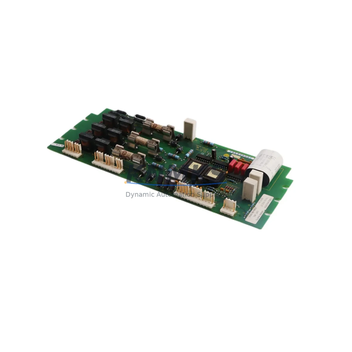
Allen-Bradley 1336-PB-SP2C Migration-Ready Power Base for Legacy Control Systems
The Allen-Bradley 1336-PB-SP2C (Part No. 74101-502-57) is a retrofit-ready power base board engineered for the 1336 PLUS series of AC variable frequency drives. As legacy 1336 PLUS installations approach end-of-service milestones, plant engineers and system integrators face mounting pressure to source verified replacement components that preserve existing control logic, minimize rewiring, and eliminate unplanned downtime. The 1336-PB-SP2C addresses this challenge directly: it is a direct form-fit-function replacement for the original power base assembly, compatible with the full 1336 PLUS drive family without requiring firmware re-flashing or backplane reconfiguration in most standard retrofit scenarios.
Before committing to a replacement, engineers should confirm the drive’s power rating and frame size against the 1336-PB-SP2C specification sheet. The power base interfaces directly with the 1336 PLUS main control board (1336-BRF-SP1 or equivalent), and terminal block wiring—including DC bus connections, gate drive signals, and thermistor feedback—must be mapped against the original wiring diagram. Incorrect terminal assignment during a hot-swap retrofit is one of the most common causes of post-installation faults; a careful point-to-point continuity check before energization is strongly recommended.
Module addressing is not applicable to this passive power base component, but the surrounding control architecture must be verified. If the 1336 PLUS drive communicates over a DeviceNet or Remote I/O network via a 1336-GM1 or 1336-GM6 communication module, the network node address and baud rate settings stored in the main control board must be documented before the power base is swapped. Loss of these parameters during a board replacement can cause the drive to drop off the network, triggering upstream PLC faults in the ControlLogix or SLC 500 controller managing the line.
Migration Compatibility Table
| Parameter | Details |
|---|---|
| Compatible Drive Series | Allen-Bradley 1336 PLUS (all standard frame sizes) |
| Part Number | 1336-PB-SP2C / 74101-502-57 |
| Replacement For | Original 1336 PLUS power base assemblies (discontinued OEM supply) |
| Backplane Interface | Direct-mount to 1336 PLUS drive chassis; no adapter required |
| Communication Compatibility | Compatible with DeviceNet (1336-GM1), Remote I/O (1336-GM6), and DH+ gateway configurations |
| Installation Requirement | Verify enclosure depth and drive frame clearance; standard 1336 PLUS cabinet footprint applies |
| Firmware Dependency | No firmware stored on power base; main control board firmware version should be ≥ 2.xx for full compatibility |
| Commissioning Focus | DC bus pre-charge verification, gate drive signal integrity check, thermistor continuity test |
| Retrofit Risk Level | Low — direct replacement with no logic changes required in standard configurations |
| Support terms | support terms confirmed by quotation — covers manufacturing defects and functional failure under normal operating conditions |
Retrofit Planning for Existing Automation Systems
A successful 1336-PB-SP2C retrofit begins well before the replacement board arrives on site. The first step is a full audit of the existing 1336 PLUS drive cabinet: document the current firmware revision on the main control board, photograph all terminal wiring, and record the parameter file using DriveExplorer or DriveExecutive software. If the site does not have a saved parameter backup, upload one immediately—this file is the single most important asset in any 1336 PLUS retrofit project.
Power supply capacity is a frequent oversight. The 1336 PLUS power base draws from the internal DC bus, but the 24 VDC control power supply feeding the I/O interface board and any installed 1336-MOD-L2E Ethernet communication module must be verified against the total load. If the existing 1746-P4 or equivalent SLC 500 power supply is already near capacity due to added I/O modules, a power budget recalculation is mandatory before the retrofit proceeds.
For installations where the 1336 PLUS drives a conveyor, pump, or compressor tied to a larger DCS or SCADA system, the HMI screen associated with the drive’s status tags must be reviewed. Rockwell FactoryTalk View or legacy PanelView terminals referencing drive fault codes, speed references, and output current will continue to function correctly after a power base swap—provided the main control board and its parameter set remain intact. If the main control board is also being replaced as part of a broader upgrade, HMI tag mapping must be re-validated against the new board’s parameter list.
In multi-drive panels where several 1336 PLUS units share a common bus or are coordinated through a 1336-BRF-SP1 control board network, replacing one power base while keeping adjacent drives online requires careful isolation. Use the drive’s enable input and hardware E-stop circuit to isolate the target drive without interrupting the broader control loop. The 1747-SN Remote I/O Scanner or 1756-DNB DeviceNet Scanner in the upstream ControlLogix rack should be placed in program mode or the relevant drive’s I/O connection inhibited before the swap to prevent nuisance faults from propagating to the PLC program.
Signal isolation is another consideration in older installations. If the 1336 PLUS receives a 4–20 mA speed reference from a legacy DCS analog output card, a signal isolator or barrier may already be in the signal path. Verify that the isolator’s loop power and ground reference remain intact after the power base replacement, particularly if the drive cabinet ground bus is disturbed during installation.
Downtime Control During System Migration
Minimizing downtime during a 1336-PB-SP2C replacement requires a structured pre-outage preparation protocol. The target window for a straightforward power base swap on a 1336 PLUS drive is two to four hours, assuming all tools, documentation, and the replacement board are staged in advance. Unplanned extensions typically result from missing parameter backups, undocumented wiring modifications made during the drive’s service life, or the discovery of secondary faults—such as a failed 1336-MOD-L2E communication module or degraded DC bus capacitors—that were masked by the primary power base failure.
To protect the original program logic, ensure the PLC controlling the drive is placed in a safe hold state before the outage begins. For ControlLogix systems, use the GSV/SSV instructions or a dedicated maintenance routine to latch the drive’s last speed reference and status. For SLC 500 systems, document the current file values in the N and F integer files associated with the drive’s I/O map. This allows the operator to verify that the drive resumes at the correct setpoint after the retrofit without requiring a full re-commissioning cycle.
After the 1336-PB-SP2C is installed and the drive is re-energized, perform a no-load test run before reconnecting the mechanical load. Verify output voltage balance across all three phases, confirm that the drive’s keypad or HMI displays the correct speed reference, and check that all fault indicators are clear. Only after a clean no-load run should the load be reconnected and a ramp-to-speed test performed under controlled conditions. This sequence protects both the new power base and the connected machinery from damage caused by undetected wiring errors.
Retrofit Support FAQ
Q: Is the 1336-PB-SP2C a direct drop-in replacement for all 1336 PLUS power base variants?
A: The 1336-PB-SP2C (74101-502-57) is designed as a direct replacement for the standard 1336 PLUS power base assembly. Confirm your drive’s frame size and original part number against the 1336 PLUS hardware service manual before ordering. For non-standard or modified drive configurations, contact our technical team with your drive’s nameplate data for a compatibility confirmation.
Q: Does the replacement board ship pre-tested?
A: Yes. Every 1336-PB-SP2C unit is functionally tested prior to shipment. Our outgoing inspection includes DC bus integrity verification, gate drive signal output checks, and thermistor circuit continuity testing. A test report is available upon request. All units are covered by a support terms confirmed by quotation against manufacturing defects and functional failure under normal operating conditions.
Q: What wiring changes are required during installation?
A: In a standard retrofit, no wiring changes are required. The 1336-PB-SP2C uses the same terminal layout and connector positions as the original power base. However, we strongly recommend photographing all existing wiring before removal and performing a point-to-point continuity check after reinstallation. If the existing wiring shows signs of heat damage or insulation degradation, replacement with appropriately rated cable is advised before re-energization.
Q: What is your stock availability and lead time?
A: The 1336-PB-SP2C is held availability confirmed by RFQ and available for immediate shipment. Standard lead time is 3–7 business days for international orders. For urgent plant-down situations, expedited shipping options are available. Contact admin@knmks.com or call +86 18359268345 to confirm current stock levels and arrange priority dispatch.
© 2026 KNMKS. All rights reserved. Original Source: https://knmks.com | Contact: admin@knmks.com | +86 18359268345
Product Identification
- Brand / Ecosystem
-
Allen-Bradley
Allen-Bradley - Model / Series
-
1336-PB-SP2C 74101-502-57
Legacy Control Series - Product Family
- Variable Frequency Drives
- Availability Status
- Available on request after model and quantity confirmation
- Inquiry Type
- B2B RFQ, replacement inquiry and project spare-part request
- Pre-Quote Check
- Exact SKU, brand, series, quantity, nameplate photos and destination country are checked before quotation
System Path
Where this product fits in the KNMKS automation structure.
Specification & Inquiry Focus
- Drive range
- AC drives, VFDs and accessories
- Common needs
- Voltage, kW/HP and load type
- Project support
- Motor control, energy saving and spares
Buyer Confirmation
Information KNMKS checks before replying.
- Exact model
- 1336-PB-SP2C 74101-502-57
- Brand / ecosystem
- Allen-Bradley
- Product family
- Variable Frequency Drives
- Application note
- Replacement, maintenance, project build or spare-part list
- Useful photos
- Nameplate, installed unit, cabinet layout or connector side
- Delivery details
- Quantity, destination country and target schedule
Document Support
Files and notes can be confirmed during quotation.
- Product photos or nameplate confirmation when available
- Packing and delivery notes before quotation confirmation
- Support scope and delivery terms confirmed per inquiry
- Export document coordination for qualified B2B requests
Inquiry Support
- Input/output voltage and kW/HP confirmation
- Energy-saving motor control inquiry
- Accessory and spare-unit support
What to Send Us
- Brand and exact model number: Allen-Bradley 1336-PB-SP2C 74101-502-57
- Quantity and required delivery time
- Application, replacement requirement or nameplate photo
- Destination country and shipping preference
RFQ Preparation
This is a product inquiry page built for RFQ communication.
Fast Model Check
Send this model to KNMKS for confirmation.
Include quantity, destination country and photos if this is a maintenance replacement. The inquiry will be saved with a reference number after submission.
Brand & Compatibility Note
KNMKS displays automation product information for well-known industrial brand ecosystems and compatible replacement references. Brand names are used for product identification and compatibility reference only; final availability and commercial terms are confirmed per quotation.
 Manufacturing
 Machine Tools
 Packaging
 Energy & Power
 PLCs & Controllers
 HMI & Displays
 Servo Systems
 Sensors