
Overview
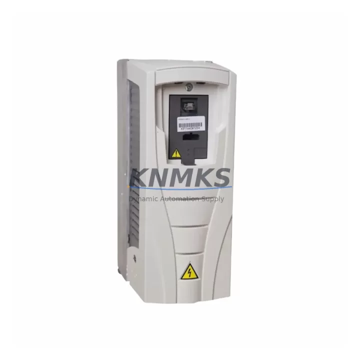
ABB ACS510-01-04A1-4 Migration-Ready VFD for Legacy Control Systems
The ABB ACS510-01-04A1-4 is a 1.5 kW, 400 V three-phase variable frequency drive engineered for direct integration into existing ACS510-series automation architectures. As legacy ACS510 installations approach end-of-service milestones, plant engineers and maintenance teams increasingly require a verified, drop-in replacement that preserves existing wiring topology, communication protocol assignments, and PLC program logic without forcing a full control cabinet redesign. The ACS510-01-04A1-4 fulfills this requirement by maintaining dimensional compatibility with the original ACS510 mounting footprint, retaining the standard I/O terminal layout, and supporting both Modbus RTU and Profibus DP fieldbus protocols natively — eliminating the need for protocol conversion gateways in most retrofit scenarios.
For facilities operating mixed-generation control environments — where a Siemens S7-300 PLC or a Rockwell ControlLogix controller manages motor drives across multiple production lines — the ACS510-01-04A1-4 integrates without requiring changes to existing SCADA tag databases or HMI screen configurations. The drive’s parameter structure mirrors the legacy ACS510 parameter map closely enough that most existing DriveWindow or DriveStudio configuration files can be imported with minimal revision, significantly reducing commissioning time during planned maintenance windows.
Pre-shipment functional testing is performed on every unit prior to dispatch. Each drive is verified for output frequency accuracy, overcurrent protection response, and fieldbus communication handshake under load simulation. Units ship with a support terms confirmed by quotation covering manufacturing defects and component failure under normal operating conditions. Multi-region stock availability supports emergency replacement timelines, with same-day dispatch available for in-stock units.
Migration Compatibility Table
| Parameter | Legacy ACS510 (Original) | ACS510-01-04A1-4 (Replacement) | Migration Note |
|---|---|---|---|
| Power Rating | 1.5 kW | 1.5 kW | Direct match — no derating required |
| Supply Voltage | 380–480 V AC, 3-phase | 380–480 V AC, 3-phase | Verify incoming supply tolerance ±10% |
| Output Current | 4.1 A nominal | 4.1 A nominal | Confirm motor nameplate FLA ≤ 4.1 A |
| Mounting Footprint | ACS510 Frame R1 | ACS510 Frame R1 | DIN rail or panel mount — no bracket change |
| Control Terminal Block | X1 standard I/O layout | X1 standard I/O layout | Existing field wiring reusable without re-termination |
| Communication Protocol | Modbus RTU / Profibus DP | Modbus RTU / Profibus DP | Retain existing fieldbus adapter (FPBA-01 / FMBA-01) |
| Fieldbus Adapter Slot | Option slot compatible | Option slot compatible | FPBA-01 Profibus adapter transfers directly |
| Parameter Backup | DriveWindow / DriveStudio | DriveWindow / DriveStudio | Export parameter file before swap; restore post-installation |
| Firmware Compatibility | ACS510 firmware baseline | Factory-loaded ACS510 firmware | Confirm firmware version matches site standard before energizing |
| Cooling Requirement | Forced air, IP21 enclosure | Forced air, IP21 enclosure | Verify cabinet airflow clearance (min. 75 mm top/bottom) |
| Support terms | — | 12 months | Covers manufacturing defects under normal operating conditions |
Retrofit Planning for Existing Automation Systems
A successful ACS510-01-04A1-4 retrofit begins well before the maintenance window opens. Engineers should start by auditing the existing control cabinet layout to confirm available installation space, verifying that the ACS510 Frame R1 footprint fits within the allocated panel section without displacing adjacent components such as the ACS-CP-C control panel or the FMBA-01 Modbus adapter module. If the original installation used an external braking resistor connected to the drive’s DC bus terminals, the resistor wiring and thermal protection relay must be documented and retained during the swap.
Terminal block wiring should be photographed and labeled before disconnection. The ACS510-01-04A1-4 preserves the standard X1 I/O terminal assignment — analog inputs AI1/AI2, digital inputs DI1–DI6, relay outputs RO1/RO2, and the 24 VDC auxiliary supply — so existing field cables can be reconnected to the same terminal positions without rewiring. For installations where the drive communicates with a Siemens S7-300 via Profibus DP using the FPBA-01 adapter, the adapter module transfers directly to the replacement unit; the GSD file and DP address assignment in the PLC hardware configuration remain unchanged.
Where the control system includes an ABB AC500 PLC managing multiple ACS510 drives over Modbus RTU on a shared RS-485 bus, the replacement drive must be assigned the same Modbus node address as the unit being retired. This is configured via parameter group 98 (Option Modules) and parameter 9802 (COMM PROT SEL) before the drive is placed online. Failure to match the node address will cause the PLC to report a communication fault and may trigger an emergency stop on the affected production line.
For sites where the ACS510 drives are supervised by a Wonderware or iFIX SCADA system, HMI tag bindings reference the drive’s Modbus register map. Because the ACS510-01-04A1-4 maintains the same register structure as the original ACS510, no SCADA tag remapping is required. However, it is advisable to verify that the SCADA system’s communication timeout settings accommodate the drive’s initialization sequence, which typically completes within 8–12 seconds after power-on. Signal isolators installed on analog reference inputs (0–10 V or 4–20 mA speed reference) should be inspected for calibration drift before the new drive is commissioned, as a miscalibrated isolator can introduce speed reference errors that are difficult to distinguish from drive parameter faults during initial startup.
Downtime Control During System Migration
Minimizing unplanned downtime during an ACS510-01-04A1-4 swap requires a structured pre-outage preparation sequence. Before the maintenance window begins, the existing drive’s full parameter set should be exported using DriveWindow Light or DriveStudio and saved to a secure location — ideally both on the engineering workstation and on a USB memory unit stored in the control cabinet. This parameter backup serves as the primary recovery tool if the replacement drive requires parameter restoration after a firmware mismatch or configuration error.
The physical swap sequence should follow a defined lockout/tagout procedure: isolate the incoming supply at the upstream circuit breaker, discharge the DC bus capacitors (minimum 5-minute wait after isolation), disconnect the motor output cables (U2/V2/W2), remove the fieldbus adapter and control panel, and then extract the drive from its mounting position. The ACS510-01-04A1-4 is installed in reverse order, with the fieldbus adapter and control panel transferred from the retired unit before the drive is energized.
First energization should be performed with the motor disconnected where possible, allowing the drive’s self-diagnostic routine to complete and confirming that the parameter restore was successful before applying load. If the site’s production schedule does not permit a no-load test, a reduced-speed jog command (typically 5–10 Hz) issued from the ACS-CP-C control panel provides a low-risk functional verification. Once the drive confirms correct rotation direction and speed reference tracking, the motor can be reconnected and the system returned to automatic control from the PLC or SCADA system. Maintaining a spare ACS510-01-04A1-4 unit on-site — pre-configured with the site’s standard parameter file — reduces future emergency replacement time to under 30 minutes.
Retrofit Support FAQ
Q1: Is the ACS510-01-04A1-4 a direct replacement for all ACS510 Frame R1 variants?
Yes. The ACS510-01-04A1-4 is dimensionally and electrically compatible with all ACS510 Frame R1 units rated at 1.5 kW / 400 V. The terminal layout, option slot configuration, and mounting hole pattern are identical to the original series. Verify the motor’s full-load ampere rating does not exceed 4.1 A before installation.
Q2: Can the existing Profibus DP or Modbus RTU fieldbus adapter be reused?
Yes. The FPBA-01 (Profibus DP) and FMBA-01 (Modbus RTU) adapter modules are mechanically and electrically compatible with the ACS510-01-04A1-4 option slot. The adapter transfers directly from the retired drive. No changes to the PLC hardware configuration, GSD file, or Modbus register assignments are required.
Q3: What pre-shipment testing is performed on each unit?
Every ACS510-01-04A1-4 unit undergoes functional testing prior to dispatch, including output frequency verification, overcurrent protection validation, and fieldbus communication handshake confirmation. Units are shipped with factory default parameters loaded and are ready for site-specific parameter configuration upon arrival.
Q4: What support terms coverage applies, and what is the typical lead time?
Each unit carries a support terms confirmed by quotation covering manufacturing defects and component failure under normal operating conditions. In-stock units are available for same-day dispatch. Multi-region inventory is maintained to support emergency replacement requirements with minimal lead time.
© 2026 KNMKS. All rights reserved.
Original Source: https://knmks.com
Contact: admin@knmks.com | +86 18359268345
Product Identification
- Brand / Ecosystem
-
ABB
ABB - Model / Series
-
ACS510-01-04A1-4
Legacy Control Series - Product Family
- Variable Frequency Drives
- Availability Status
- Available on request after model and quantity confirmation
- Inquiry Type
- B2B RFQ, replacement inquiry and project spare-part request
- Pre-Quote Check
- Exact SKU, brand, series, quantity, nameplate photos and destination country are checked before quotation
System Path
Where this product fits in the KNMKS automation structure.
Specification & Inquiry Focus
- Drive range
- AC drives, VFDs and accessories
- Common needs
- Voltage, kW/HP and load type
- Project support
- Motor control, energy saving and spares
Buyer Confirmation
Information KNMKS checks before replying.
- Exact model
- ACS510-01-04A1-4
- Brand / ecosystem
- ABB
- Product family
- Variable Frequency Drives
- Application note
- Replacement, maintenance, project build or spare-part list
- Useful photos
- Nameplate, installed unit, cabinet layout or connector side
- Delivery details
- Quantity, destination country and target schedule
Document Support
Files and notes can be confirmed during quotation.
- Product photos or nameplate confirmation when available
- Packing and delivery notes before quotation confirmation
- Support scope and delivery terms confirmed per inquiry
- Export document coordination for qualified B2B requests
Inquiry Support
- Input/output voltage and kW/HP confirmation
- Energy-saving motor control inquiry
- Accessory and spare-unit support
What to Send Us
- Brand and exact model number: ABB ACS510-01-04A1-4
- Quantity and required delivery time
- Application, replacement requirement or nameplate photo
- Destination country and shipping preference
RFQ Preparation
This is a product inquiry page built for RFQ communication.
Fast Model Check
Send this model to KNMKS for confirmation.
Include quantity, destination country and photos if this is a maintenance replacement. The inquiry will be saved with a reference number after submission.
Brand & Compatibility Note
KNMKS displays automation product information for well-known industrial brand ecosystems and compatible replacement references. Brand names are used for product identification and compatibility reference only; final availability and commercial terms are confirmed per quotation.
 Manufacturing
 Machine Tools
 Packaging
 Energy & Power
 PLCs & Controllers
 HMI & Displays
 Servo Systems
 Sensors