
Overview
Siemens A5F00118608-006 Migration-Ready HMI Panel: Legacy System Retrofit & Upgrade
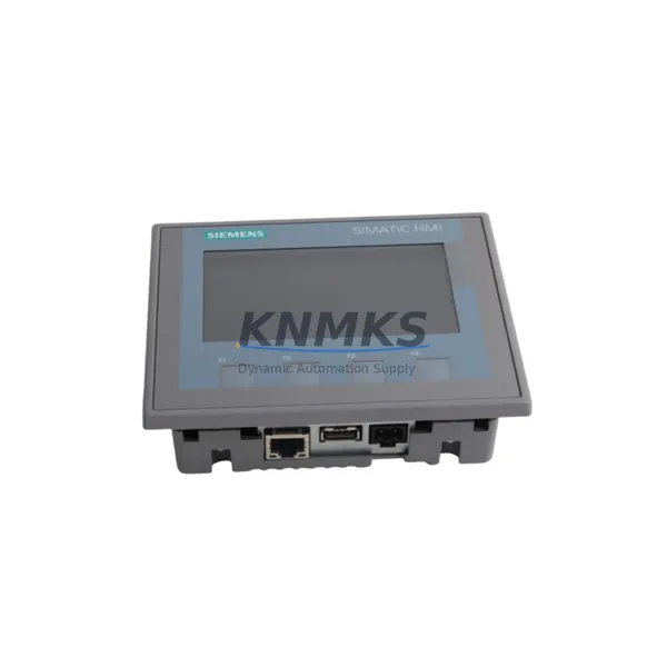
The Siemens A5F00118608-006 is a migration-ready HMI operator panel engineered for direct replacement of discontinued or end-of-life touchscreen interfaces in SIMATIC S7-300 and S7-400 control architectures. As legacy automation systems approach their end-of-support lifecycle, plant engineers and maintenance teams face increasing pressure to source compatible spare parts that preserve existing program logic, HMI screen layouts, and communication links without triggering a full-line shutdown. The A5F00118608-006 addresses this challenge by offering verified electrical compatibility, matched panel cutout dimensions, and support for the MPI/PROFIBUS DP communication protocols commonly found in older S7 installations.
When planning a retrofit around this unit, the first step is to confirm the power supply capacity of the existing control cabinet. The A5F00118608-006 operates on a 24 V DC supply, and the existing SITOP PSU or equivalent power module must be verified to deliver sufficient current headroom after accounting for all connected I/O modules and communication cards. In many legacy cabinets, the original SITOP power supply has been running at near-capacity for years; a retrofit is an ideal opportunity to audit load distribution and, if necessary, replace the power module with a higher-rated unit before commissioning the new HMI.
Terminal wiring is the next critical checkpoint. The A5F00118608-006 uses a standard 9-pin Sub-D connector for MPI/PROFIBUS DP and a separate 24 V DC power terminal block. Technicians should verify that the existing cable harness — including the PROFIBUS DP cable with its characteristic violet sheath and 9-pin connectors — is undamaged and properly terminated with bus termination resistors at both ends of the segment. If the legacy installation used an older PC adapter or programming cable for HMI configuration, a current USB/MPI adapter or PROFIBUS USB adapter will be required to re-download the WinCC flexible or TIA Portal project to the replacement panel.
Backplane interface and rack compatibility are not applicable to this standalone panel-mount HMI, but the module address assignment within the PROFIBUS segment must be confirmed before power-up. The A5F00118608-006 must be assigned the same PROFIBUS node address as the unit it replaces; this is configured via the panel’s startup menu or through the project download. Failure to match the node address will prevent the S7-300 or S7-400 CPU — such as a CPU 315-2 DP or CPU 416-3 DP — from establishing communication with the HMI, resulting in a communication fault alarm on the controller.
Program and screen compatibility is a key concern for maintenance teams. If the original HMI project was created in WinCC flexible 2008 or an earlier version, it can be migrated to TIA Portal WinCC using the integrated migration wizard, though screen objects, scripts, and tag connections should be reviewed after migration. Where the original project files are unavailable, the replacement HMI can be configured from scratch using the existing S7 tag database exported from STEP 7 or TIA Portal. In either case, all alarm messages, trend displays, and recipe screens should be validated against the physical process before returning the line to production.
Communication link verification extends beyond the HMI itself. In multi-node PROFIBUS segments, the addition or replacement of any device can affect bus timing and signal integrity. After installing the A5F00118608-006, engineers should use a PROFIBUS diagnostic tool or the CPU’s diagnostic buffer to confirm that all nodes — including distributed I/O racks such as ET 200M or ET 200S remote I/O stations, variable frequency drives, and other field devices — are communicating without errors. If the segment was previously operating near its maximum node count or cable length, a PROFIBUS repeater may be required to restore signal margin.
Installation space confirmation is straightforward for panel-mount HMIs: the A5F00118608-006 requires a standard panel cutout matching the TP series form factor, with adequate depth behind the panel face for the rear housing and cable routing. Technicians should verify that the control cabinet door has sufficient clearance and that the gasket seal is intact to maintain the IP65 front-face protection rating in environments exposed to dust or wash-down.
Firmware version compatibility should be checked before commissioning. The replacement unit should be updated to the firmware version specified in the HMI project properties to ensure that all screen functions, communication drivers, and recipe management features operate as designed. Firmware updates are performed via USB or Ethernet using the ProSave utility or TIA Portal’s device maintenance functions.
All units supplied by KNMKS undergo pre-shipment functional testing, including power-on verification, display calibration check, and communication port continuity test. Each A5F00118608-006 is covered by a support terms confirmed by quotation against manufacturing defects, with global shipping available from in-stock inventory to minimize procurement lead times for urgent maintenance situations.
Migration Compatibility Table
| Parameter | A5F00118608-006 (Replacement) | Typical Legacy Unit | Notes |
|---|---|---|---|
| Communication Interface | MPI / PROFIBUS DP (9-pin Sub-D) | MPI / PROFIBUS DP | Direct protocol match; verify node address |
| Power Supply | 24 V DC | 24 V DC | Verify SITOP or cabinet PSU current capacity |
| Panel Cutout | TP series standard cutout | TP series standard cutout | Confirm depth clearance behind panel face |
| Front Protection Rating | IP65 | IP65 | Inspect gasket seal before installation |
| Engineering Software | WinCC flexible / TIA Portal WinCC | WinCC flexible 2008 or earlier | Use migration wizard; validate all screens post-migration |
| Compatible Controllers | S7-300, S7-400 series CPUs | S7-300, S7-400 series CPUs | CPU 315-2 DP, CPU 416-3 DP confirmed compatible |
| Commissioning Tool | USB/MPI adapter or PROFIBUS USB adapter | PC adapter (serial/USB) | Current adapter required for project download |
| Support terms | 12 Months | — | Covers manufacturing defects; global shipping |
Retrofit Planning for Existing Automation Systems
A successful retrofit centered on the A5F00118608-006 typically involves coordinating several interdependent components within the same control cabinet or PROFIBUS segment. The CPU module — most commonly a Siemens CPU 315-2 DP or CPU 317-2 DP mounted on an S7-300 rack — remains in place, and the HMI replacement is performed as a hot-swap during a planned maintenance window. However, the surrounding infrastructure must be assessed in advance.
The SITOP PSU 24 V DC power supply feeding the HMI and associated I/O should be load-tested before the retrofit. If the cabinet also houses an SM 321 digital input module or SM 322 digital output module on the same 24 V rail, the total current draw must be recalculated to confirm that the power supply can support the replacement HMI without voltage droop. In aging installations, capacitor degradation in the power supply can cause intermittent undervoltage faults that are difficult to diagnose after the new HMI is installed.
For systems that include a CP 343-1 Ethernet communication processor or a CP 342-5 PROFIBUS DP master module, the network topology should be documented before the retrofit begins. If the HMI communicates via MPI while other devices use PROFIBUS DP on the same backplane, the bus parameters — baud rate, HSA, and retry limits — must be consistent across all nodes. A PROFIBUS segment with mixed baud rates is a common source of intermittent communication faults in legacy systems.
Where the existing installation includes an ET 200M distributed I/O station connected via PROFIBUS DP, the station’s IM 153-2 interface module address and slot configuration should be recorded before any work begins. The A5F00118608-006 HMI project will reference these I/O addresses directly in its tag database, and any address conflict introduced during the retrofit will cause process visualization errors that may not be immediately obvious during initial commissioning.
If the control system includes a signal isolator or intrinsic safety barrier between the HMI analog outputs and field instruments, the isolator’s input impedance and loop power requirements should be verified against the replacement HMI’s analog output specifications. This is particularly relevant in hazardous area installations where the isolator forms part of the certified protection concept.
Finally, if a programming cable or MPI/USB adapter is not already available on site, it should be sourced as part of the retrofit kit. The project download to the A5F00118608-006 cannot be performed without a compatible adapter, and delays in sourcing this accessory are a common cause of extended commissioning time in field retrofit projects.
Downtime Control During System Migration
Minimizing unplanned downtime is the primary operational concern in any HMI retrofit. For the A5F00118608-006, the recommended approach is to prepare the replacement unit fully before the maintenance window begins. This means downloading the validated HMI project to the new panel in the workshop, verifying all screen navigation and alarm displays against the original project documentation, and confirming that the PROFIBUS node address is correctly set before the unit is transported to site.
During the maintenance window, the sequence should be: isolate the control cabinet, photograph the existing wiring and terminal connections, remove the legacy HMI, install the A5F00118608-006 using the existing panel cutout and mounting hardware, reconnect the PROFIBUS DP cable and 24 V DC power terminals, restore power, and verify communication with the S7 CPU before releasing the line. The entire physical swap can typically be completed in under 30 minutes by a trained technician, provided the replacement unit has been pre-configured.
The original PLC program logic in the S7-300 or S7-400 CPU is not affected by the HMI replacement. The CPU continues to execute its control program independently of the HMI communication status, which means that process control is maintained even during the brief period when the HMI is disconnected. This is an important point to communicate to operations teams who may be concerned about process continuity during the swap.
Post-installation, the commissioning checklist should include: confirmation of all HMI screen displays against the process P&ID, verification of all alarm setpoints and acknowledgment functions, a test of any recipe or data logging functions, and a 30-minute observation period under normal operating conditions before signing off the retrofit. Any firmware update should be applied before the project download, not after, to avoid compatibility issues between the project and the panel firmware.
Retrofit Support FAQ
Q1: Is the A5F00118608-006 a direct drop-in replacement for the original unit?
In most SIMATIC S7-300 and S7-400 installations, yes. The A5F00118608-006 shares the same panel cutout dimensions, 24 V DC power input, and MPI/PROFIBUS DP communication interface as the original TP series HMI it replaces. The HMI project must be re-downloaded to the replacement unit; it does not retain the previous unit’s project data. Verify the PROFIBUS node address and bus parameters before power-up.
Q2: What commissioning steps are required after installation?
After physical installation and wiring, connect a USB/MPI adapter or PROFIBUS USB adapter to the panel’s programming port and download the validated HMI project using WinCC flexible or TIA Portal WinCC. Set the PROFIBUS node address to match the original unit. Power on the panel and confirm communication with the S7 CPU via the HMI’s online diagnostics. Validate all screen displays, alarm functions, and any data logging or recipe management features before returning the system to production.
Q3: How is wiring compatibility confirmed before ordering?
Document the existing PROFIBUS DP cable connector type (9-pin Sub-D), the 24 V DC power terminal block layout, and the panel cutout dimensions from the legacy HMI’s nameplate or installation drawing. Compare these against the A5F00118608-006 datasheet. In the majority of TP series installations, no wiring modifications are required. If the legacy installation used a non-standard cable assembly, a short adapter harness may be needed.
Q4: What does the support terms confirmed by quotation cover, and what is the stock availability?
The support terms confirmed by quotation cover manufacturing defects in materials and workmanship from the date of shipment. Each unit undergoes pre-shipment functional testing including power-on verification, display check, and communication port continuity test. KNMKS maintains in-stock inventory of the A5F00118608-006 to support urgent maintenance requirements, with global shipping available. For current stock levels and lead times, contact admin@knmks.com or call +86 18359268345.
© 2026 KNMKS. All rights reserved.
Original Source: https://knmks.com
Contact: admin@knmks.com | +86 18359268345
Product Identification
- Brand / Ecosystem
-
Siemens
Siemens - Model / Series
- A5F00118608-006
- Product Family
- HMI & Displays
- Availability Status
- Available on request after model and quantity confirmation
- Inquiry Type
- B2B RFQ, replacement inquiry and project spare-part request
- Pre-Quote Check
- Exact SKU, brand, series, quantity, nameplate photos and destination country are checked before quotation
System Path
Where this product fits in the KNMKS automation structure.
Specification & Inquiry Focus
- Display range
- Operator panels and touch screens
- Common needs
- Screen size, interface and version matching
- Project support
- Retrofit, spare unit and panel replacement
Buyer Confirmation
Information KNMKS checks before replying.
- Exact model
- A5F00118608-006
- Brand / ecosystem
- Siemens
- Product family
- HMI & Displays
- Application note
- Replacement, maintenance, project build or spare-part list
- Useful photos
- Nameplate, installed unit, cabinet layout or connector side
- Delivery details
- Quantity, destination country and target schedule
Document Support
Files and notes can be confirmed during quotation.
- Product photos or nameplate confirmation when available
- Packing and delivery notes before quotation confirmation
- Support scope and delivery terms confirmed per inquiry
- Export document coordination for qualified B2B requests
Inquiry Support
- Panel size and interface confirmation
- Replacement unit inquiry for discontinued HMIs
- Protective packaging for display shipment
What to Send Us
- Brand and exact model number: Siemens A5F00118608-006
- Quantity and required delivery time
- Application, replacement requirement or nameplate photo
- Destination country and shipping preference
RFQ Preparation
This is a product inquiry page built for RFQ communication.
Fast Model Check
Send this model to KNMKS for confirmation.
Include quantity, destination country and photos if this is a maintenance replacement. The inquiry will be saved with a reference number after submission.
Brand & Compatibility Note
KNMKS displays automation product information for well-known industrial brand ecosystems and compatible replacement references. Brand names are used for product identification and compatibility reference only; final availability and commercial terms are confirmed per quotation.
 Manufacturing
 Machine Tools
 Packaging
 Energy & Power
 PLCs & Controllers
 Servo Systems
 Variable Frequency Drives
 Sensors