
Overview
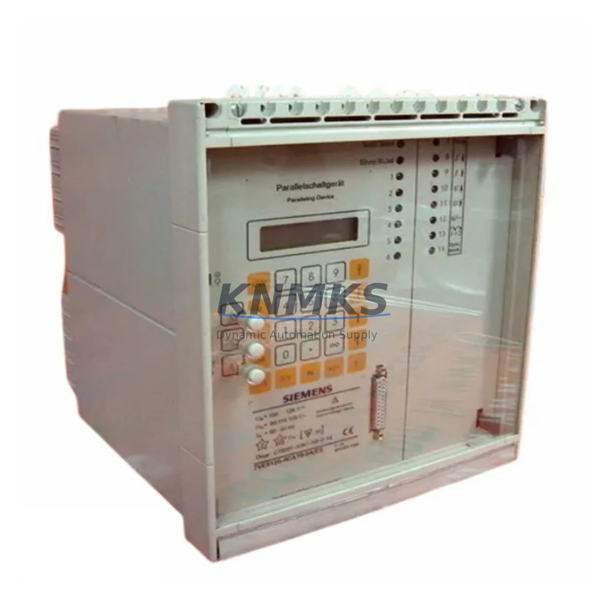
Siemens 7VE5120-4CA10-0A/FF Migration-Ready Synchronizing Relay: Legacy System Retrofit and Control Upgrade
The Siemens 7VE5120-4CA10-0A/FF is a synchronizing relay designed for generator and bus-tie synchronization in medium-voltage switchgear and power distribution systems. As aging SIPROTEC 4 and earlier-generation synchronizing modules reach end-of-life, the 7VE5120-4CA10-0A/FF provides a verified drop-in replacement path for facilities managing legacy control infrastructure. This unit supports direct substitution in existing SIPROTEC relay panels, retaining the original terminal layout and binary I/O assignments where the host panel has not been structurally modified.
For maintenance engineers managing unplanned outages or scheduled overhauls, the 7VE5120-4CA10-0A/FF reduces procurement lead time risk. Units are pre-shipment tested against factory acceptance criteria, covering synchronization accuracy, voltage window thresholds, frequency difference limits, and phase angle tolerances before dispatch. Each unit ships with a support terms confirmed by quotation covering manufacturing defects and functional performance under rated operating conditions.
Migration Compatibility Table
| Parameter | Detail |
|---|---|
| SKU / Order Number | 7VE5120-4CA10-0A/FF |
| Series | SIPROTEC 7VE51 |
| Function | Synchronizing Relay — Generator / Bus-Tie Sync |
| Typical Replacement Target | Older 7VE51xx variants, legacy sync check relays in SIPROTEC 4 panels |
| Terminal / Wiring Compatibility | Retains standard SIPROTEC terminal block layout; verify auxiliary voltage and binary input wiring before energizing |
| Auxiliary Voltage | Confirm panel auxiliary supply matches rated input range (AC/DC); mismatch is the most common commissioning error |
| Communication Interface | Check PROFIBUS or IEC 60870-5-103 port configuration against existing SCADA or DCS mapping |
| Mounting / Installation | Standard 19″ rack or flush-panel mounting; confirm cutout dimensions match existing relay bay |
| Firmware | Verify firmware version compatibility with DIGSI 4 or DIGSI 5 parameterization tool before parameter upload |
| Commissioning Focus | Synchronization window settings, dead-bus / dead-line logic, CB close command timing |
| Pre-Shipment Test | Functional test completed; sync accuracy, voltage and frequency window thresholds verified |
| Support terms | 12 months from date of shipment |
Retrofit Planning for Existing Automation Systems
A successful retrofit of the 7VE5120-4CA10-0A/FF into an existing switchgear panel requires a structured review of the surrounding control architecture. Before removing the legacy synchronizing relay, engineers should document the existing parameter set using DIGSI 4 — capturing synchronization window settings, voltage and frequency thresholds, phase angle limits, and CB close pulse duration. This parameter file serves as the baseline for the replacement unit and significantly reduces re-commissioning time.
Power supply capacity in the relay panel must be verified before installation. The 7VE5120-4CA10-0A/FF draws auxiliary power from the panel DC bus; if the existing SITOP PSU or equivalent DC power supply is already loaded near capacity by other protection relays — such as a 7SJ62 overcurrent relay or a 7UT63 differential protection unit sharing the same panel — a load calculation should be completed before adding the replacement unit. Undersized auxiliary supply is a common cause of intermittent relay resets during high-load switching events.
Binary input and output wiring should be mapped against the existing terminal diagram. In panels where a 7XV5650 serial communication module or a CP-2016 communications processor handles SCADA integration, the binary output assignments of the synchronizing relay feed directly into the interlocking logic. Any change in output relay numbering between the old and replacement unit must be reflected in the PLC or RTU logic before the panel is re-energized. Where the control system uses a SIMATIC S7-300 or S7-400 PLC for sequence-of-events logging, the input module address assignments should be confirmed against the existing hardware configuration in STEP 7 or TIA Portal.
For facilities running IEC 61850-based substation automation, the 7VE5120-4CA10-0A/FF logical node mapping should be reviewed against the existing SCD file. If the legacy relay was configured with a GOOSE subscription for bus voltage supervision, the replacement unit’s IED configuration must replicate the same GOOSE dataset references to maintain interlocking continuity without modifying the station-level configuration unnecessarily.
Where the retrofit involves a broader control cabinet upgrade — for example, replacing an aging SIPROTEC 4 bay controller with a SIPROTEC 5 device — the synchronizing relay replacement is typically sequenced after the bay controller swap to allow the new controller’s parameterization to be validated first. This sequencing reduces the number of simultaneous variables during commissioning and makes fault isolation faster if issues arise during energization.
Downtime Control During System Migration
Minimizing outage duration during synchronizing relay replacement depends on preparation quality before the maintenance window opens. The most effective approach is to complete all parameter extraction, wiring documentation, and spare parts staging — including the replacement 7VE5120-4CA10-0A/FF, any required terminal adapters, and updated wiring ferrules — before the planned outage begins. A pre-tested parameter file loaded onto a laptop running DIGSI 4 allows the replacement unit to be parameterized and functionally tested on the bench before it enters the panel.
During the outage, the sequence should follow: isolate auxiliary supply to the relay bay, remove the legacy synchronizing relay, install the 7VE5120-4CA10-0A/FF, reconnect terminal wiring per the verified diagram, restore auxiliary supply, upload the pre-prepared parameter file, and perform a bench-level functional check of the synchronization window logic before closing the CB. This sequence, when executed against a pre-validated checklist, typically keeps the relay replacement within a two-to-four hour maintenance window for a single bay.
Where the plant cannot tolerate a full outage, a staged approach is possible: the legacy relay can be left in service while the replacement unit is parameterized and tested in parallel on a test bench using a relay test set. Once the replacement unit passes all acceptance tests, the switchover is limited to the physical swap and wiring reconnection, reducing live outage time to under one hour in most cases. All original program logic in the associated PLC or DCS remains unchanged during this process, as the synchronizing relay replacement does not require modifications to the upstream control program provided the binary I/O assignments are preserved.
Retrofit Support FAQ
Q: Is the 7VE5120-4CA10-0A/FF a direct replacement for earlier 7VE51 variants?
A: In most cases, yes. The 7VE5120-4CA10-0A/FF shares the same housing format and terminal block layout as earlier 7VE51xx variants. However, firmware version and parameter set compatibility should be verified using DIGSI 4 before uploading an existing parameter file from an older unit. Minor differences in function block availability between firmware versions may require parameter adjustments.
Q: What wiring checks are required before energizing the replacement unit?
A: Verify auxiliary voltage polarity and level, binary input wiring against the existing terminal diagram, voltage transformer secondary connections (phase-to-phase or phase-to-neutral as required by the sync function), and output relay wiring to the CB close circuit. Confirm that any external blocking inputs — such as a dead-bus permissive from the bus voltage relay — are correctly connected before enabling the synchronization function.
Q: Has the unit been tested before shipment?
A: Yes. Each 7VE5120-4CA10-0A/FF unit undergoes pre-shipment functional testing covering synchronization accuracy, voltage and frequency window thresholds, and output relay operation. Test records are available on request. The unit ships with a support terms confirmed by quotation from the date of shipment.
Q: What is the stock and lead time situation for this SKU?
A: Units are available from current inventory. For volume requirements or long-term supply commitments supporting multi-site retrofit programs, contact the sales team to discuss scheduled delivery and inventory reservation options.
© 2026 KNMKS. All rights reserved.
Original Source: https://knmks.com
Contact: admin@knmks.com | +86 18359268345
Product Identification
- Brand / Ecosystem
-
Siemens
Siemens - Model / Series
- 7VE5120-4CA10-0A/FF
- Product Family
- Relays & Interface
- Availability Status
- Available on request after model and quantity confirmation
- Inquiry Type
- B2B RFQ, replacement inquiry and project spare-part request
- Pre-Quote Check
- Exact SKU, brand, series, quantity, nameplate photos and destination country are checked before quotation
System Path
Where this product fits in the KNMKS automation structure.
Specification & Inquiry Focus
- Interface range
- Relays, isolation and signal modules
- Common needs
- Coil voltage and contact rating
- Project support
- Panel wiring and signal protection
Buyer Confirmation
Information KNMKS checks before replying.
- Exact model
- 7VE5120-4CA10-0A/FF
- Brand / ecosystem
- Siemens
- Product family
- Relays & Interface
- Application note
- Replacement, maintenance, project build or spare-part list
- Useful photos
- Nameplate, installed unit, cabinet layout or connector side
- Delivery details
- Quantity, destination country and target schedule
Document Support
Files and notes can be confirmed during quotation.
- Product photos or nameplate confirmation when available
- Packing and delivery notes before quotation confirmation
- Support scope and delivery terms confirmed per inquiry
- Export document coordination for qualified B2B requests
Inquiry Support
- Relay base and module matching
- Signal isolation and protection options
- Panel accessory inquiry support
What to Send Us
- Brand and exact model number: Siemens 7VE5120-4CA10-0A/FF
- Quantity and required delivery time
- Application, replacement requirement or nameplate photo
- Destination country and shipping preference
RFQ Preparation
This is a product inquiry page built for RFQ communication.
Fast Model Check
Send this model to KNMKS for confirmation.
Include quantity, destination country and photos if this is a maintenance replacement. The inquiry will be saved with a reference number after submission.
Brand & Compatibility Note
KNMKS displays automation product information for well-known industrial brand ecosystems and compatible replacement references. Brand names are used for product identification and compatibility reference only; final availability and commercial terms are confirmed per quotation.
 Manufacturing
 Machine Tools
 Packaging
 Energy & Power

 PLCs & Controllers
 HMI & Displays
 Servo Systems
 Variable Frequency Drives