
Overview
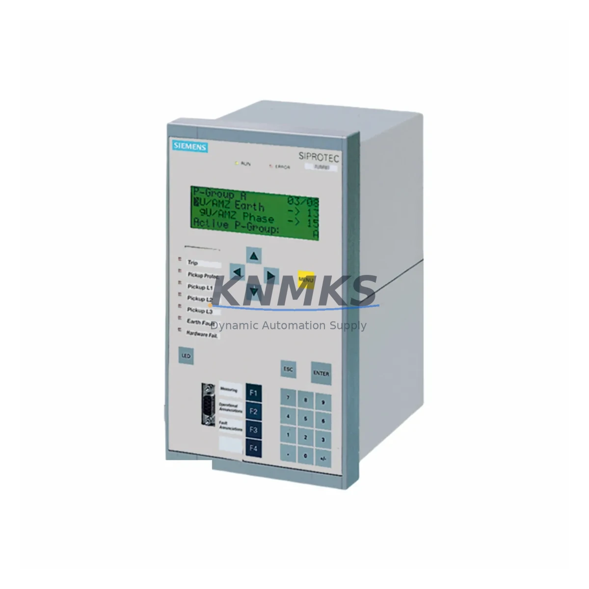
Siemens 7UT6125-5EB20-1AA0/BB Migration-Ready Differential Relay for Legacy Control Systems
The Siemens 7UT6125-5EB20-1AA0/BB is a SIPROTEC 5 series numerical differential protection relay engineered for transformer, generator, and motor protection in medium- and high-voltage substations. As a direct migration-ready replacement for the discontinued SIPROTEC 4 7UT612 platform, this unit enables engineering teams to modernize aging protection schemes without redesigning primary CT circuits, terminal wiring, or substation communication infrastructure. With native support for IEC 61850 Edition 2, PROFIBUS DP, and DNP3, the 7UT6125-5EB20-1AA0/BB integrates seamlessly into both legacy SCADA environments and modern digital substation architectures.
Before initiating a retrofit from the 7UT612 to the 7UT6125-5EB20-1AA0/BB, engineers must verify several critical parameters. Power supply capacity at the relay panel must accommodate the SIPROTEC 5 auxiliary voltage range (typically 24–250 V DC). Terminal wiring from existing CT and VT circuits should be mapped against the new terminal assignment diagram, as the SIPROTEC 5 chassis uses a different I/O module layout compared to the SIPROTEC 4 rack. The binary input and output assignments must be re-mapped in DIGSI 5, Siemens’ engineering tool for SIPROTEC 5 configuration, which replaces the DIGSI 4 environment used with the 7UT612. Protection function parameters — including differential characteristic slopes, restraint settings, and harmonic blocking thresholds — must be re-entered manually, as DIGSI 4 project files are not directly importable into DIGSI 5. HMI display pages and local panel mimic diagrams will require reconfiguration to reflect the new relay’s function block structure. Communication link continuity must be confirmed, particularly where the existing substation LAN uses IEC 61850 GOOSE messaging for inter-relay interlocking or where legacy serial PROFIBUS DP links connect to RTUs or DCS gateways.
Installation space confirmation is essential: the 7UT6125-5EB20-1AA0/BB uses the SIPROTEC 5 modular housing, which may differ in panel cutout dimensions from the SIPROTEC 4 7UT612 flush-mount case. Adapter plates are available for standard 19-inch rack and flush-panel installations. Firmware version compatibility should be reviewed against the substation’s IEC 61850 SCL configuration files (SCD/ICD) to ensure the relay’s capability description aligns with the station bus configuration tool’s expectations.
Migration Compatibility Table
| Parameter | Legacy: 7UT612 (SIPROTEC 4) | Replacement: 7UT6125-5EB20-1AA0/BB (SIPROTEC 5) |
|---|---|---|
| Engineering Tool | DIGSI 4 | DIGSI 5 (V7.90+) |
| Communication Protocol | IEC 61850 Ed.1, PROFIBUS DP, IEC 60870-5-103 | IEC 61850 Ed.2, PROFIBUS DP, DNP3, Modbus TCP |
| CT Input Compatibility | 1A / 5A selectable | 1A / 5A selectable — CT reuse confirmed |
| Housing / Panel Cutout | SIPROTEC 4 flush-mount (7XP20) | SIPROTEC 5 modular (adapter plate may be required) |
| Binary I/O Mapping | Fixed I/O on base unit | Modular I/O via plug-in modules — re-mapping required |
| Parameter Migration | DIGSI 4 project file | Manual re-entry in DIGSI 5 — no direct import |
| HMI / Local Display | SIPROTEC 4 graphical display | SIPROTEC 5 touchscreen HMI — page reconfiguration required |
| Firmware Compatibility | SIPROTEC 4 firmware | SIPROTEC 5 firmware — verify SCL/SCD file alignment |
| Auxiliary Voltage | 24–250 V DC / 115–230 V AC | 24–250 V DC / 100–230 V AC — verify panel supply |
| Replacement Recommendation | Direct functional replacement with re-commissioning. Suitable for transformer, generator, and motor differential protection applications. | |
| Commissioning Focus | CT polarity check, differential characteristic verification, GOOSE link test, binary I/O functional test, HMI page validation | |
| Support terms | support terms confirmed by quotation | Pre-shipment functional test included | |
Retrofit Planning for Existing Automation Systems
A successful retrofit from the SIPROTEC 4 platform to the 7UT6125-5EB20-1AA0/BB requires a structured approach that accounts for the full protection and control chain within the substation panel. The relay does not operate in isolation — it interfaces with a range of adjacent components whose compatibility must be confirmed before the outage window begins.
On the power supply side, the existing DC distribution board feeding the relay panel must be verified to deliver stable auxiliary voltage within the SIPROTEC 5 operating range. Where the legacy 7UT612 was powered from a shared 110 V DC bus alongside other SIPROTEC 4 devices such as the 7SJ64 overcurrent relay or the 7SD522 line differential relay, the new relay’s inrush current profile during startup should be reviewed against the fuse or MCB rating on that DC branch.
For communication infrastructure, the 7UT6125-5EB20-1AA0/BB connects to the station bus via an integrated Ethernet port supporting IEC 61850 Ed.2 GOOSE and MMS. Where the substation LAN was originally configured for SIPROTEC 4 IEC 61850 Ed.1 devices, the SCL configuration files must be updated using a station configuration tool such as Siemens’ SICAM PAS or a third-party IEC 61850 configurator. If the existing RTU or DCS gateway communicates via PROFIBUS DP — common in older Siemens SICAM or WinCC-based SCADA systems — the PROFIBUS DP slave address and GSD file must be updated to reflect the SIPROTEC 5 device profile.
The I/O module configuration within the SIPROTEC 5 chassis is modular. Engineers should confirm that the required number of binary inputs and outputs matches the available plug-in I/O modules ordered with the 7UT6125-5EB20-1AA0/BB. Where the legacy scheme used the 7UT612’s fixed I/O for trip coil supervision, breaker failure initiation, or lockout relay (86) activation, equivalent function blocks must be assigned to the new modular I/O in DIGSI 5. Signal isolators or interposing relays may be required where the existing wiring uses voltage levels outside the SIPROTEC 5 binary input thresholds.
For sites where the protection scheme includes a 7XV5662 or similar SIPROTEC communication module for inter-relay pilot wire differential protection, or where a 6MD66 bay controller coordinates protection and control functions, the impact of replacing the 7UT612 on the overall bay-level logic must be assessed. Similarly, if a 6GK7 SCALANCE switch or CP 343-1 communication processor manages the substation LAN, VLAN and QoS settings may need adjustment to prioritize GOOSE traffic from the new relay.
Downtime Control During System Migration
Minimizing outage duration during the transition from the 7UT612 to the 7UT6125-5EB20-1AA0/BB requires pre-outage preparation that eliminates as many on-site tasks as possible. The DIGSI 5 project — including all protection function parameters, I/O assignments, communication settings, and HMI page layouts — should be fully configured, simulated, and peer-reviewed before the relay arrives on site. A factory acceptance test (FAT) or bench test using the actual relay unit, performed with a secondary injection test set such as the Omicron CMC 356, confirms that differential characteristic curves, harmonic blocking, and trip output timing meet the protection coordination study requirements before the panel is opened.
During the outage, the original 7UT612 configuration printout and wiring diagrams should be available for reference. Terminal-by-terminal wiring transfer, rather than bulk rewiring, reduces the risk of polarity errors on CT circuits. After physical installation, a CT polarity and ratio check using a secondary injection set confirms that the differential element will operate correctly under load. GOOSE link status should be verified from the station HMI or DIGSI 5 online mode before the protection is declared in service.
Where the protected asset — transformer, generator, or motor — cannot be taken out of service for an extended period, a staged migration approach is possible: the 7UT6125-5EB20-1AA0/BB can be installed in monitoring mode with the trip outputs isolated, allowing the protection logic to be validated under live load conditions before the legacy 7UT612 is decommissioned. This approach preserves control continuity and allows the commissioning team to confirm differential current measurements, restraint current calculations, and communication link integrity without exposing the system to an unprotected interval.
All pre-shipment units are functionally tested before dispatch. In-stock availability supports emergency replacement scenarios where unplanned outages require same-week delivery. The support terms confirmed by quotation cover the relay against manufacturing defects and provides a defined support path for post-commissioning issues.
Retrofit Support FAQ
Q1: Is the 7UT6125-5EB20-1AA0/BB a direct drop-in replacement for the Siemens 7UT612?
A: Functionally yes — both provide numerical transformer differential protection with harmonic restraint and CT reuse. However, the SIPROTEC 5 platform requires re-commissioning: DIGSI 5 replaces DIGSI 4, I/O modules are modular rather than fixed, and IEC 61850 SCL files must be updated. Panel cutout dimensions may differ, and an adapter plate may be required for flush-mount installations.
Q2: Can existing CT wiring be reused without modification?
A: In most cases, yes. The 7UT6125-5EB20-1AA0/BB accepts 1A and 5A CT inputs, matching the 7UT612’s input range. CT polarity and ratio must be verified by secondary injection after rewiring to the new terminal layout. Where CT circuits include interposing CTs or summation CTs, the wiring diagram must be reviewed against the new terminal assignment.
Q3: What commissioning tests are required before returning the relay to service?
A: Minimum commissioning tests include: CT polarity and ratio check by secondary injection, differential characteristic verification at multiple operating points, harmonic blocking test (2nd and 5th harmonic), binary I/O functional test for all trip and alarm outputs, GOOSE link integrity test from the station HMI, and communication link test to the SCADA/RTU. A full commissioning report should be retained for asset management records.
Q4: What support terms and stock availability does KNMKS provide for this relay?
A: All 7UT6125-5EB20-1AA0/BB units supplied by KNMKS carry a support terms confirmed by quotation covering manufacturing defects. Each unit undergoes pre-shipment functional testing before dispatch. In-stock units are available for same-week global dispatch, supporting both planned retrofit projects and emergency replacement requirements. Contact admin@knmks.com or +86 18359268345 for lead time and availability confirmation.
© 2026 KNMKS. All rights reserved.
Original Source: https://knmks.com
Contact: admin@knmks.com | +86 18359268345
Product Identification
- Brand / Ecosystem
-
SIEMENS
Siemens - Model / Series
- 7UT6125-5EB20-1AA0/BB
- Product Family
- Relays & Interface
- Availability Status
- Available on request after model and quantity confirmation
- Inquiry Type
- B2B RFQ, replacement inquiry and project spare-part request
- Pre-Quote Check
- Exact SKU, brand, series, quantity, nameplate photos and destination country are checked before quotation
System Path
Where this product fits in the KNMKS automation structure.
Specification & Inquiry Focus
- Interface range
- Relays, isolation and signal modules
- Common needs
- Coil voltage and contact rating
- Project support
- Panel wiring and signal protection
Buyer Confirmation
Information KNMKS checks before replying.
- Exact model
- 7UT6125-5EB20-1AA0/BB
- Brand / ecosystem
- SIEMENS
- Product family
- Relays & Interface
- Application note
- Replacement, maintenance, project build or spare-part list
- Useful photos
- Nameplate, installed unit, cabinet layout or connector side
- Delivery details
- Quantity, destination country and target schedule
Document Support
Files and notes can be confirmed during quotation.
- Product photos or nameplate confirmation when available
- Packing and delivery notes before quotation confirmation
- Support scope and delivery terms confirmed per inquiry
- Export document coordination for qualified B2B requests
Inquiry Support
- Relay base and module matching
- Signal isolation and protection options
- Panel accessory inquiry support
What to Send Us
- Brand and exact model number: SIEMENS 7UT6125-5EB20-1AA0/BB
- Quantity and required delivery time
- Application, replacement requirement or nameplate photo
- Destination country and shipping preference
RFQ Preparation
This is a product inquiry page built for RFQ communication.
Fast Model Check
Send this model to KNMKS for confirmation.
Include quantity, destination country and photos if this is a maintenance replacement. The inquiry will be saved with a reference number after submission.
Brand & Compatibility Note
KNMKS displays automation product information for well-known industrial brand ecosystems and compatible replacement references. Brand names are used for product identification and compatibility reference only; final availability and commercial terms are confirmed per quotation.
 Manufacturing
 Machine Tools
 Packaging
 Energy & Power

 PLCs & Controllers
 HMI & Displays
 Servo Systems
 Variable Frequency Drives