
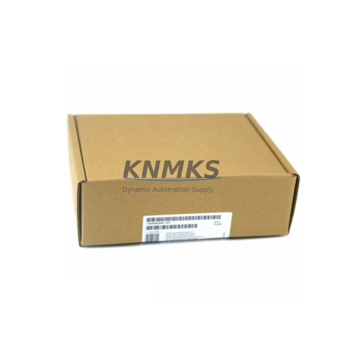
Overview
Siemens 7RE2800-0CA00 Migration-Ready Voltage Balance Relay: Legacy System Migration and Compatible Upgrade
The Siemens 7RE2800-0CA00 is a SIPROTEC-series voltage balance relay engineered for both new installations and the modernization of aging protection systems. As industrial facilities worldwide accelerate the retirement of first- and second-generation numerical protection relays, the 7RE2800-0CA00 has become a preferred drop-in replacement for obsolete electromechanical and early digital voltage supervision devices. Its compact DIN-rail and panel-mount form factor, combined with broad compatibility across SIPROTEC 4 and SIPROTEC Compact platforms, makes it a practical solution for control cabinet upgrades without requiring full rack redesign.
When planning a retrofit around the 7RE2800-0CA00, engineers must verify several critical parameters before committing to a cutover. Power supply capacity is the first checkpoint: confirm that the existing auxiliary bus — typically 24 VDC, 48 VDC, or 110/220 VAC — can sustain the relay’s quiescent and peak operating current without tripping upstream protection. Terminal wiring compatibility is equally important; the 7RE2800-0CA00 uses a standard screw-terminal block layout, but legacy installations may use ring-lug or ferrule terminations that require adapter sleeves or rewiring of the terminal strip. Backplane interface and slot addressing must be confirmed if the relay is installed within a SIPROTEC chassis alongside modules such as the SIPROTEC 7SJ85 overcurrent relay or the 7UT85 transformer differential relay — each slot assignment affects the DIGSI 5 device address map and must be updated in the project configuration before download.
Program compatibility is a frequent concern during migration. If the legacy system used DIGSI 4 parameter files, these must be exported and re-imported or manually recreated in DIGSI 5, as direct migration of .dp4 files is not supported without the DIGSI 4 Migration Tool. HMI screen updates are also required: any SCADA or local HMI panels — including Siemens SIMATIC HMI TP700 or OP panels — that display voltage balance status will need their tag databases and faceplates revised to reflect the new relay’s data point structure. Communication link verification is mandatory for IEC 61850 GOOSE and MMS configurations; the 7RE2800-0CA00 supports IEC 61850 Edition 2, and existing SCL/SCD files must be updated to include the new IED description before the substation automation system can re-establish logical node communication.
Installation space confirmation is a practical step that is often overlooked. The 7RE2800-0CA00’s physical dimensions must be cross-referenced against the available panel cutout or DIN-rail segment, particularly in densely populated control cabinets where adjacent modules — such as a SITOP PSU100S power supply module or a CP 343-1 Ethernet communication processor — leave limited clearance. Firmware version alignment is the final pre-commissioning check: ensure the relay ships with or is updated to the firmware revision specified in the project’s type-tested protection scheme documentation, as certain protection function parameters are firmware-version-dependent.
Migration Compatibility Table
| Parameter | Detail |
|---|---|
| SKU / Model | 7RE2800-0CA00 |
| Brand / Series | Siemens SIPROTEC |
| Function | Voltage Balance Relay (Voltage Supervision) |
| Communication Protocol | IEC 61850 Ed.2 (GOOSE / MMS), PROFIBUS, Modbus RTU |
| Auxiliary Supply | 24–250 VDC / 115–230 VAC (wide-range) |
| Mounting | Panel flush-mount / DIN-rail (35 mm) |
| Terminal Type | Screw terminals (ring-lug / ferrule adapter recommended for legacy wiring) |
| Backplane / Rack Compatibility | SIPROTEC 4 chassis; SIPROTEC Compact standalone |
| Configuration Tool | DIGSI 5 (DIGSI 4 Migration Tool required for legacy .dp4 files) |
| Typical Legacy Replacements | Electromechanical voltage balance relays; early SIPROTEC 4 7RE26xx series |
| Installation Space | Verify panel cutout dimensions before ordering |
| Firmware Compatibility | Confirm firmware revision against project type-test documentation |
| Commissioning | DIGSI 5 parameter download, GOOSE subscription test, secondary injection test |
| Support terms | 12 Months — covers manufacturing defects, functional failure, and DOA replacement |
| Origin | Germany |
Retrofit Planning for Existing Automation Systems
A successful retrofit centered on the 7RE2800-0CA00 typically involves coordinating several interdependent components within the same control cabinet or protection panel. On the power distribution side, engineers should audit the SITOP PSU100S or equivalent 24 VDC power supply module to confirm it can absorb the additional load of the new relay without exceeding its rated output current. If the cabinet also houses a SIPROTEC 7SJ85 feeder protection relay sharing the same auxiliary bus, load balancing across the DC distribution bar must be recalculated.
For I/O expansion requirements, the 7RE2800-0CA00’s binary input and output count should be mapped against the existing wiring schedule. In cases where the legacy relay provided more output contacts than the replacement, a supplementary I/O module — such as a Siemens SIPROTEC 7XV5662 binary I/O expansion module — may be required to maintain full trip and alarm circuit continuity. Signal isolators should be inserted on any analog measurement inputs sourced from legacy transducers that operate at non-standard signal levels, preventing ground loop interference that could cause spurious voltage balance trips.
Communication infrastructure upgrades are often triggered by the relay replacement. If the existing substation LAN uses copper Fast Ethernet and the migration plan calls for IEC 61850 GOOSE messaging, a managed Ethernet switch with VLAN and QoS support must be confirmed in the network topology. The SIMATIC NET CP 343-1 Lean communication processor, if present in an adjacent S7-300 controller rack, may need its firmware updated to correctly parse the new relay’s MMS reports. Programming cables — specifically the DIGSI USB-to-RS232 adapter or the RJ45 service interface cable — should be on-site during commissioning to allow direct relay access independent of the substation LAN.
Where the retrofit involves a full control cabinet rebuild, the mechanical layout should account for the 7RE2800-0CA00 alongside the SIPROTEC 7UT85 transformer differential relay and any associated COMBIFLEX or SIGUT terminal blocks. Proper cable segregation between CT/VT secondary circuits and communication cables is essential to avoid induced noise on the measurement inputs.
Downtime Control During System Migration
Minimizing unplanned outage duration is the primary operational constraint in any live protection system retrofit. The recommended approach for replacing a legacy voltage balance relay with the 7RE2800-0CA00 is a staged cutover: pre-configure and bench-test the new relay off-line using DIGSI 5 before the scheduled maintenance window, so that the on-site installation is limited to physical mounting, terminal reconnection, and a final parameter download verification.
Preserving the original program logic requires exporting all existing relay settings — including protection function parameters, binary I/O assignments, and communication configuration — before decommissioning the legacy device. Where DIGSI 4 parameter files exist, the DIGSI 4 Migration Tool should be used to generate a baseline DIGSI 5 project, which is then reviewed and corrected by the protection engineer before being loaded to the 7RE2800-0CA00. This approach eliminates the risk of manual re-entry errors in critical protection thresholds such as voltage differential pickup levels and time-delay settings.
Maintaining field control continuity during the cutover window requires temporary bridging of trip and alarm output circuits. Portable relay test sets can be used to simulate the voltage balance relay’s output contacts during the physical swap, ensuring that upstream circuit breaker trip coils and SCADA alarm inputs remain in a defined state throughout the installation. After the 7RE2800-0CA00 is energized and its DIGSI 5 configuration is confirmed, a secondary injection test using a relay test set verifies that all protection functions operate within the specified tolerances before the system is returned to service. Total planned downtime for a single-relay replacement using this methodology is typically two to four hours, depending on terminal count and communication re-commissioning complexity.
Retrofit Support FAQ
Q1: Is the 7RE2800-0CA00 a direct replacement for the Siemens 7RE26xx series voltage balance relays?
The 7RE2800-0CA00 is functionally compatible with the 7RE26xx series and is the recommended upgrade path for SIPROTEC 4 installations. Terminal wiring layouts are similar but not identical — a wiring comparison using the respective relay manuals is required before reconnection. DIGSI 5 must be used for configuration; legacy DIGSI 4 parameter files require migration using the DIGSI 4 Migration Tool.
Q2: What pre-shipment testing is performed on the 7RE2800-0CA00?
Each unit undergoes functional testing prior to dispatch, including auxiliary supply energization, binary I/O verification, and communication port continuity checks. Units are shipped with a test report. The support terms confirmed by quotation cover manufacturing defects, functional failure under normal operating conditions, and dead-on-arrival (DOA) replacement with priority dispatch.
Q3: Can the 7RE2800-0CA00 be used in IEC 61850 GOOSE-based protection schemes?
Yes. The relay supports IEC 61850 Edition 2, including GOOSE publishing and subscription. The IED’s SCL description file must be imported into the substation configuration tool (e.g., DIGSI 5 or a third-party IEC 61850 configurator) and the SCD file updated before GOOSE communication can be established. Existing GOOSE subscriptions on peer relays must be re-mapped to the new IED reference.
Q4: What is the typical lead time and stock availability?
The 7RE2800-0CA00 is held availability confirmed by RFQ for immediate dispatch. Standard orders ship within 1–3 business days. For urgent retrofit projects requiring same-day dispatch, contact admin@knmks.com or call +86 18359268345 to confirm real-time availability. Bulk orders for multi-panel retrofit projects are accommodated with volume pricing on request.
© 2026 KNMKS. All rights reserved.
Original Source: https://knmks.com
Contact: admin@knmks.com | +86 18359268345
Product Identification
- Brand / Ecosystem
-
Siemens
Siemens - Model / Series
- 7RE2800-0CA00
- Product Family
- Relays & Interface
- Availability Status
- Available on request after model and quantity confirmation
- Inquiry Type
- B2B RFQ, replacement inquiry and project spare-part request
- Pre-Quote Check
- Exact SKU, brand, series, quantity, nameplate photos and destination country are checked before quotation
System Path
Where this product fits in the KNMKS automation structure.
Specification & Inquiry Focus
- Interface range
- Relays, isolation and signal modules
- Common needs
- Coil voltage and contact rating
- Project support
- Panel wiring and signal protection
Buyer Confirmation
Information KNMKS checks before replying.
- Exact model
- 7RE2800-0CA00
- Brand / ecosystem
- Siemens
- Product family
- Relays & Interface
- Application note
- Replacement, maintenance, project build or spare-part list
- Useful photos
- Nameplate, installed unit, cabinet layout or connector side
- Delivery details
- Quantity, destination country and target schedule
Document Support
Files and notes can be confirmed during quotation.
- Product photos or nameplate confirmation when available
- Packing and delivery notes before quotation confirmation
- Support scope and delivery terms confirmed per inquiry
- Export document coordination for qualified B2B requests
Inquiry Support
- Relay base and module matching
- Signal isolation and protection options
- Panel accessory inquiry support
What to Send Us
- Brand and exact model number: Siemens 7RE2800-0CA00
- Quantity and required delivery time
- Application, replacement requirement or nameplate photo
- Destination country and shipping preference
RFQ Preparation
This is a product inquiry page built for RFQ communication.
Fast Model Check
Send this model to KNMKS for confirmation.
Include quantity, destination country and photos if this is a maintenance replacement. The inquiry will be saved with a reference number after submission.
Brand & Compatibility Note
KNMKS displays automation product information for well-known industrial brand ecosystems and compatible replacement references. Brand names are used for product identification and compatibility reference only; final availability and commercial terms are confirmed per quotation.
 Manufacturing
 Machine Tools
 Packaging
 Energy & Power

 PLCs & Controllers
 HMI & Displays
 Servo Systems
 Variable Frequency Drives