
Overview
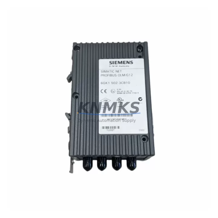
Siemens 6GK1502-3CB10 Migration-Ready PROFIBUS OLM/G12: Legacy Control System Retrofit & Upgrade
The Siemens 6GK1502-3CB10 OLM/G12 (Optical Link Module) is a fiber-optic repeater designed for PROFIBUS DP networks, enabling reliable data transmission at up to 12 Mbps over glass fiber. Originally deployed in SINEC L2 and early SIMATIC S5/S7 automation architectures, this module remains a critical component for engineers managing aging control infrastructure. Whether you are replacing a failed unit in a running production line, upgrading a legacy SINEC L2 ring topology to a modern SIMATIC S7-300 or S7-400 backbone, or extending the service life of an existing PROFIBUS segment, the 6GK1502-3CB10 provides a direct, drop-in solution with no firmware changes required on the host controller.
Before installing a replacement 6GK1502-3CB10, engineers should verify several key parameters to ensure a seamless cutover. Power supply compatibility is the first checkpoint: the OLM/G12 requires a 24 VDC supply with sufficient current capacity on the cabinet rail — confirm that the existing SITOP PSU or equivalent power module can sustain the additional load, particularly if the cabinet also houses a CP 342-5 communications processor or a DP/PA coupler. Terminal wiring on the 9-pin Sub-D PROFIBUS connector must be inspected for correct pin assignment (A-line, B-line, and shield), especially on older installations where field wiring may not conform to current EN 50170 standards.
Backplane and rack considerations are equally important. In S7-300 installations, the OLM/G12 is typically mounted on a 35 mm DIN rail adjacent to the CPU rack rather than on the backplane itself, so installation space in the control cabinet must be confirmed before ordering. For S7-400 systems using IM 460/461 interface modules for distributed I/O expansion, the fiber segment topology must be mapped to ensure the OLM/G12 is positioned correctly within the ring or line structure. Module addressing on the PROFIBUS segment does not require reconfiguration of the OLM itself — it is transparent to the network — but the STEP 7 or TIA Portal hardware configuration should be reviewed to confirm that DP slave addresses remain consistent after the swap.
Program compatibility is not affected by replacing the OLM/G12, as the module operates at the physical layer only. However, if the legacy system uses a CP 5611 or CP 5613 PROFIBUS card on the engineering station for online diagnostics, engineers should confirm that the fiber patch cables (ST or BFOC connectors, depending on the OLM variant) are in good condition and that optical power budgets are within specification. HMI screens built on WinCC or SIMATIC Panel (TP/OP series) that display PROFIBUS network status should be tested after replacement to verify that diagnostic data from the DP master is still being received correctly.
Communication link integrity should be validated using a PROFIBUS tester or the diagnostic functions available in STEP 7 NetPro / TIA Portal after the module is installed. Pay particular attention to bus termination: if the 6GK1502-3CB10 is at a segment end, the integrated termination resistors must be activated. Firmware version compatibility is not a concern for the OLM/G12 as it contains no user-programmable firmware, but the connected DP master (e.g., CPU 315-2 DP or CPU 414-2 DP) should be running a firmware revision that supports the configured baud rate and watchdog timeout settings.
All units supplied by KNMKS are tested prior to shipment, sourced from verified industrial channels, and covered by a support terms confirmed by quotation. Stock is maintained to support urgent replacement requirements with short lead times.
Migration Compatibility Table
| Parameter | Details |
|---|---|
| SKU / Order Number | 6GK1502-3CB10 |
| Series | SINEC / SIMATIC NET OLM |
| Function | PROFIBUS DP Optical Link Module (Glass Fiber) |
| Baud Rate | 9.6 kbps – 12 Mbps (auto-detecting) |
| Fiber Connector | BFOC/ST (2 × optical ports) |
| Power Supply | 24 VDC (18–32 V), approx. 120 mA |
| Installation | 35 mm DIN rail, IP20 |
| Compatible Systems | SIMATIC S5, S7-300, S7-400, SINEC L2 |
| Replaces / Compatible With | 6GK1502-3CA10, 6GK1502-3CB00 (earlier revisions) |
| Communication Protocol | PROFIBUS DP (EN 50170 / IEC 61158) |
| Retrofit Recommendation | Direct replacement; verify fiber patch cable condition and bus termination |
| Commissioning Note | No address configuration required; validate with STEP 7 / TIA Portal diagnostics post-installation |
| Support terms | 12 months from date of shipment |
Retrofit Planning for Existing Automation Systems
A successful retrofit involving the 6GK1502-3CB10 typically occurs within a broader control system modernization project. In many legacy S5-based lines, the migration path leads from a CPU 948 or CPU 928B controller through an intermediate PROFIBUS DP gateway to a modern S7-400 CPU 414-3 DP or CPU 416-3 DP. During this transition, the OLM/G12 serves as the fiber backbone for the PROFIBUS ring, connecting distributed ET 200M I/O stations or ET 200S islands that handle field-level signals. Engineers should map each ET 200M station’s slot configuration and I/O addresses before the cutover to avoid address conflicts in the new STEP 7 project.
Power distribution within the cabinet must also be reassessed. If the existing SITOP PSU 24V/10A is already loaded by the CPU rack, communications processors, and field devices, adding or replacing an OLM/G12 may require a supplementary SITOP PSU 24V/5A on a dedicated rail segment. Signal isolators — such as those used on analog input channels feeding the S7-300 SM 331 analog input module — should be checked for ground loop issues that can introduce noise on the PROFIBUS segment after a topology change.
For systems that include an S7-300 CP 342-5 or CP 343-5 for PROFIBUS master functionality, the GSD file for each DP slave must be re-imported into the TIA Portal project if migrating from STEP 7 Classic. Programming cables such as the PC Adapter USB A2 or MPI/PROFIBUS adapter should be on hand during commissioning to allow direct CPU access for online monitoring and program download without relying on the network segment being replaced.
Downtime Control During System Migration
Minimizing production downtime during a PROFIBUS OLM replacement requires careful pre-staging. The replacement 6GK1502-3CB10 should be bench-tested with a PROFIBUS tester before the maintenance window begins, confirming optical power levels on both fiber ports. A backup of the CPU program (including data blocks and system data) should be saved to a memory card or PC before any hardware is disturbed, preserving the original logic in case a rollback is needed.
During the swap, the PROFIBUS ring should be broken at the OLM/G12 connection points rather than at the DP slave terminals, reducing the risk of disturbing field wiring. If the system uses a redundant PROFIBUS ring topology (supported by the OLM/G12’s integrated redundancy manager function), the redundancy path should be disabled in software before the module is removed to prevent the network from entering a fault state during the transition. After the new module is installed and fiber connections are secured, the redundancy function can be re-enabled and verified through the OLM’s LED status indicators before the maintenance window closes.
HMI panels connected via MPI or PROFIBUS should be monitored for communication alarms during the first 15–30 minutes of operation after the replacement. If WinCC Runtime or a SIMATIC TP/OP panel reports persistent communication errors, the first diagnostic step is to check the OLM’s PROFIBUS port LEDs and verify bus termination at both segment ends. Keeping the original failed OLM/G12 on-site until the replacement has been confirmed stable provides an additional safety net during the commissioning phase.
Retrofit Support FAQ
Q1: Is the 6GK1502-3CB10 a direct replacement for the 6GK1502-3CB00?
Yes. The 6GK1502-3CB10 is the current revision of the OLM/G12 and is functionally compatible with the earlier 6GK1502-3CB00. No changes to PROFIBUS addressing, baud rate settings, or DP master configuration are required. Verify that the fiber connector type (BFOC/ST) matches the existing patch cables before installation.
Q2: What commissioning steps are required after installing the replacement module?
After physical installation, confirm 24 VDC power is present and the PWR LED is green. Connect fiber cables and check that the OLM’s optical port LEDs indicate active links. Use STEP 7 or TIA Portal online diagnostics to verify that all DP slaves on the segment are accessible. If the system uses redundant ring topology, confirm that the redundancy manager LED shows a closed ring before returning the system to production.
Q3: Does KNMKS test units before shipment?
Yes. All 6GK1502-3CB10 units are powered-on and functionally tested prior to dispatch. Units are supplied with a support terms confirmed by quotation covering manufacturing defects and operational failures under normal industrial use conditions. Expedited shipping is available for urgent replacement requirements.
Q4: What is the stock availability and lead time?
KNMKS maintains inventory of the 6GK1502-3CB10 to support short-notice replacement needs. Standard orders are processed and dispatched within 1–3 business days. For large-quantity or project-based requirements, contact our sales team to confirm availability and arrange a dedicated allocation.
© 2026 KNMKS. All rights reserved.
Original Source: https://knmks.com
Contact: admin@knmks.com | +86 18359268345
Product Identification
- Brand / Ecosystem
-
Siemens
Siemens - Model / Series
-
6GK1502-3CB10
SIMATIC Series - Product Family
- Communication Modules
- Availability Status
- Available on request after model and quantity confirmation
- Inquiry Type
- B2B RFQ, replacement inquiry and project spare-part request
- Pre-Quote Check
- Exact SKU, brand, series, quantity, nameplate photos and destination country are checked before quotation
System Path
Where this product fits in the KNMKS automation structure.
Specification & Inquiry Focus
- Network range
- Ethernet, fieldbus and gateway modules
- Common needs
- Protocol, port and controller family
- Project support
- Machine networking and data integration
Buyer Confirmation
Information KNMKS checks before replying.
- Exact model
- 6GK1502-3CB10
- Brand / ecosystem
- Siemens
- Product family
- Communication Modules
- Application note
- Replacement, maintenance, project build or spare-part list
- Useful photos
- Nameplate, installed unit, cabinet layout or connector side
- Delivery details
- Quantity, destination country and target schedule
Document Support
Files and notes can be confirmed during quotation.
- Product photos or nameplate confirmation when available
- Packing and delivery notes before quotation confirmation
- Support scope and delivery terms confirmed per inquiry
- Export document coordination for qualified B2B requests
Inquiry Support
- Industrial Ethernet and fieldbus module inquiry
- Protocol compatibility review
- Integration project inquiry support
What to Send Us
- Brand and exact model number: Siemens 6GK1502-3CB10
- Quantity and required delivery time
- Application, replacement requirement or nameplate photo
- Destination country and shipping preference
RFQ Preparation
This is a product inquiry page built for RFQ communication.
Fast Model Check
Send this model to KNMKS for confirmation.
Include quantity, destination country and photos if this is a maintenance replacement. The inquiry will be saved with a reference number after submission.
Brand & Compatibility Note
KNMKS displays automation product information for well-known industrial brand ecosystems and compatible replacement references. Brand names are used for product identification and compatibility reference only; final availability and commercial terms are confirmed per quotation.
 Manufacturing
 Machine Tools
 Packaging
 Energy & Power
 PLCs & Controllers
 HMI & Displays
 Servo Systems
 Variable Frequency Drives