
Overview
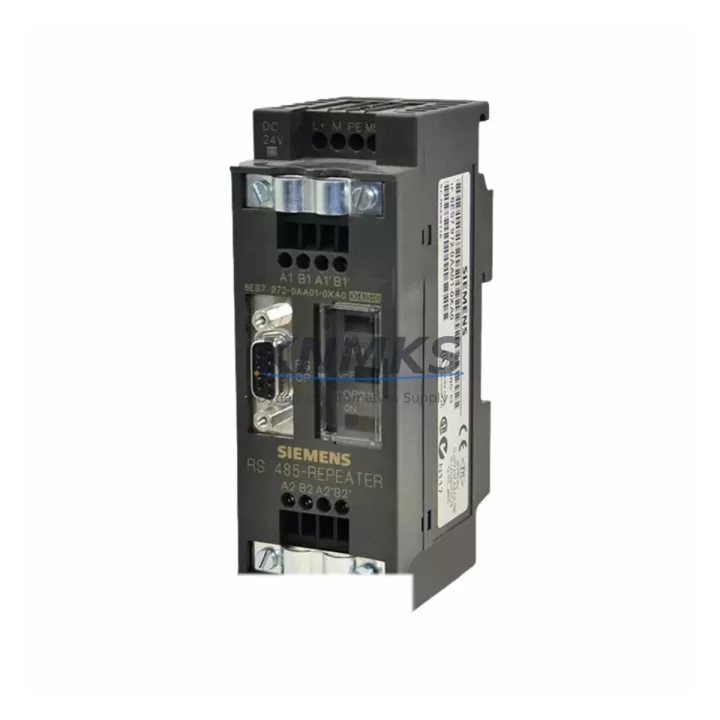
Siemens 6ES7972-0AA01-0XA0 Migration-Ready PROFIBUS DP Repeater for Legacy Control Systems
The Siemens 6ES7972-0AA01-0XA0 is a PROFIBUS DP Repeater designed for signal amplification and segment extension within SIMATIC S7-300 and S7-400 automation networks. As legacy PROFIBUS-based control architectures approach end-of-life, this repeater remains a critical component for engineers executing phased migration strategies — enabling continued operation of existing field devices while new control infrastructure is staged in parallel. Whether you are consolidating aging control cabinets, extending a PROFIBUS segment to accommodate additional I/O nodes, or bridging two electrically isolated network segments during a retrofit, the 6ES7972-0AA01-0XA0 provides the signal integrity and bus isolation required to maintain deterministic communication across the migration window.
Before deploying this repeater as a replacement unit, engineers should verify several key parameters: bus termination resistor settings on both segments, maximum cable length per segment (up to 1,200 m at 9.6 kbps, reducing to 100 m at 12 Mbps), power supply voltage (24 VDC nominal), and the number of nodes per segment (maximum 31 per segment, 62 total across both segments). Terminal wiring follows the standard PROFIBUS DB9 or screw-terminal convention depending on the installation variant; confirm the existing cabinet wiring harness matches before substitution. The module occupies a standard DIN rail slot and does not require a backplane slot assignment, making it compatible with both S7-300 rack-mounted configurations and standalone cabinet installations.
In systems where the 6ES7972-0AA01-0XA0 is being introduced to replace a failed or discontinued repeater, the replacement procedure should include: recording the current baud rate setting (DIP switch or software-configured), verifying bus address assignments for all downstream slaves, and confirming that the STEP 7 or TIA Portal hardware configuration reflects the updated network topology. If the legacy project was created in STEP 7 Classic (v5.x), ensure the GSD file for each field device is still accessible before modifying the hardware configuration, as re-importing GSD files after topology changes can affect symbolic addressing in the program blocks.
Migration Compatibility Table
| Parameter | Specification / Recommendation |
|---|---|
| Compatible Controllers | SIMATIC S7-300, S7-400, S7-1500 (via PROFIBUS CM) |
| Bus Protocol | PROFIBUS DP (EN 50170) |
| Supported Baud Rates | 9.6 kbps – 12 Mbps (auto-detection) |
| Max Nodes per Segment | 31 (62 total across both segments) |
| Power Supply | 24 VDC (20.4 – 28.8 VDC) |
| Installation | DIN rail, no backplane slot required |
| Terminal Wiring | Screw terminal or DB9 — verify existing harness |
| Electrical Isolation | Yes — galvanic isolation between segments |
| Replacement for | 6ES7972-0AA00-0XA0 (prior revision), discontinued repeater variants |
| Programming Tool | STEP 7 v5.x / TIA Portal V13 and above |
| Firmware Compatibility | No firmware update required — hardware-configured |
| Pre-Shipment Testing | Function-verified before dispatch |
| Support terms | 12 Months — covers functional defects from date of shipment |
Retrofit Planning for Existing Automation Systems
A successful PROFIBUS retrofit begins well before the physical swap. During the planning phase, engineers should audit the full network topology: identify all DP master stations (typically a CPU 315-2 DP, CPU 317-2 DP, or a CP 342-5 communications processor), enumerate all DP slave devices (distributed I/O racks, drives, valve terminals), and document the current segment boundaries. The 6ES7972-0AA01-0XA0 is commonly deployed at the boundary between two segments where cable length limits have been reached or where electrical isolation is required between a control cabinet and a field junction box.
When the retrofit involves expanding I/O capacity, engineers frequently add ET 200M or ET 200S distributed I/O stations to the extended segment. These stations connect via IM 153-x interface modules and may require additional DP addresses to be reserved in the master configuration. If the existing CPU is a legacy S7-300 unit with a fixed DP master interface, verify that the total number of DP slaves does not exceed the CPU’s configured limit before adding new nodes downstream of the repeater.
Power distribution within the control cabinet should also be reviewed. The 6ES7972-0AA01-0XA0 draws power from the 24 VDC bus rail; confirm that the existing PS 307 or PS 305 power supply module has sufficient residual capacity after accounting for all connected modules. In cabinets where the power budget is tight, a supplementary SITOP PSU100S power supply unit is often added to feed the repeater and any new I/O expansion modules independently.
For systems that include SIMATIC HMI panels (TP700, TP900, or legacy OP series) connected via PROFIBUS, the repeater insertion point must be chosen carefully to avoid splitting the HMI’s DP connection from its associated CPU. After the repeater is installed, verify HMI communication by cycling through all process screens and confirming that all tag values update correctly. If the HMI project was created in WinCC flexible, re-download the project to the panel after any hardware topology change to ensure the communication parameters are synchronized.
Cable routing and shielding practices are equally important during retrofit. PROFIBUS cables should use the standard violet-jacketed, shielded twisted-pair cable (e.g., Siemens 6XV1830-0EH10), with the shield connected to the PE rail at one end only per segment to avoid ground loops. When routing new cable segments through existing cable trays, maintain physical separation from high-voltage power cables to minimize electromagnetic interference.
Downtime Control During System Migration
Minimizing production downtime during a PROFIBUS repeater replacement requires a structured approach. Begin by scheduling the swap during a planned maintenance window and preparing a rollback plan: retain the original repeater on-site until the replacement has been validated in operation. Before powering down the segment, export the current STEP 7 or TIA Portal project to a backup archive and document the current diagnostic status of all DP slaves using the hardware diagnostics function in the programming software.
During the physical swap, label all terminal connections before disconnecting wiring. The 6ES7972-0AA01-0XA0 uses clearly marked terminals for A-line, B-line, and shield connections on both segments; cross-reference these against the original wiring diagram to ensure correct polarity. After reconnection, power up the segment and observe the BF (Bus Fault) LED on the repeater and on the CPU’s DP interface — both should extinguish within a few seconds if the bus is correctly terminated and all slaves are responding.
If any DP slave fails to come online after the swap, use the diagnostic buffer in STEP 7 or TIA Portal to identify the station address of the non-responding device. Common causes include incorrect bus termination at the new segment end, a baud rate mismatch if the repeater’s auto-detection did not lock correctly, or a wiring polarity reversal on one of the segments. Resolving these issues typically requires less than 15 minutes and does not require program modifications, preserving the original control logic intact throughout the migration.
For critical production lines where even a brief interruption is unacceptable, consider a hot-standby approach: install the new repeater in parallel with the existing unit on a temporary cable spur, validate communication on the new segment, then cut over by transferring the field device connections one at a time. This technique is particularly effective when migrating from an older 6ES7972-0AA00-0XA0 revision to the current 0AA01 revision without halting the production process.
Retrofit Support FAQ
Q1: Is the 6ES7972-0AA01-0XA0 a direct drop-in replacement for the 6ES7972-0AA00-0XA0?
Yes. The 0AA01 revision is the current production successor to the 0AA00 revision. Mechanical dimensions, terminal layout, DIN rail mounting, and electrical specifications are identical. No hardware configuration changes are required in STEP 7 or TIA Portal when substituting one revision for the other.
Q2: What pre-shipment testing is performed on this unit?
Each 6ES7972-0AA01-0XA0 is function-verified prior to dispatch. Testing confirms power-up behavior, LED status indication, and bus signal pass-through at standard PROFIBUS baud rates. Units are shipped with original or equivalent packaging to prevent transit damage.
Q3: Can this repeater be used in a mixed S7-300 / S7-1500 migration environment?
Yes. The 6ES7972-0AA01-0XA0 operates at the physical layer and is protocol-transparent. It can bridge PROFIBUS DP segments regardless of whether the DP master is an S7-300 CPU with integrated DP interface, an S7-400 with a CP 443-5 Extended, or an S7-1500 equipped with a CM 1542-5 communications module. The repeater does not interpret or modify DP telegrams.
Q4: What does the support terms confirmed by quotation cover, and what is the stock availability?
The support terms confirmed by quotation cover functional defects from the date of shipment. Units availability confirmed by RFQ are available for immediate dispatch with standard lead times of 3–7 business days for international destinations. For urgent requirements, expedited shipping options are available. Contact admin@knmks.com or call +86 18359268345 to confirm current stock levels and delivery schedules.
© 2026 KNMKS. All rights reserved.
Original Source: https://knmks.com
Contact: admin@knmks.com | +86 18359268345
Product Identification
- Brand / Ecosystem
-
Siemens
Siemens - Model / Series
-
6ES7972-0AA01-0XA0
SIMATIC Series - Product Family
- PLCs & Controllers
- Availability Status
- Available on request after model and quantity confirmation
- Inquiry Type
- B2B RFQ, replacement inquiry and project spare-part request
- Pre-Quote Check
- Exact SKU, brand, series, quantity, nameplate photos and destination country are checked before quotation
System Path
Where this product fits in the KNMKS automation structure.
Specification & Inquiry Focus
- Control platform
- PLC, PAC and modular controllers
- Common needs
- CPU, rack, power and I/O expansion
- Project support
- Replacement, cabinet build and maintenance
Buyer Confirmation
Information KNMKS checks before replying.
- Exact model
- 6ES7972-0AA01-0XA0
- Brand / ecosystem
- Siemens
- Product family
- PLCs & Controllers
- Application note
- Replacement, maintenance, project build or spare-part list
- Useful photos
- Nameplate, installed unit, cabinet layout or connector side
- Delivery details
- Quantity, destination country and target schedule
Document Support
Files and notes can be confirmed during quotation.
- Product photos or nameplate confirmation when available
- Packing and delivery notes before quotation confirmation
- Support scope and delivery terms confirmed per inquiry
- Export document coordination for qualified B2B requests
Inquiry Support
- Model cross-checking before quotation
- CPU, power, rack and expansion module matching
- Support for replacement and project inquiry
What to Send Us
- Brand and exact model number: Siemens 6ES7972-0AA01-0XA0
- Quantity and required delivery time
- Application, replacement requirement or nameplate photo
- Destination country and shipping preference
RFQ Preparation
This is a product inquiry page built for RFQ communication.
Fast Model Check
Send this model to KNMKS for confirmation.
Include quantity, destination country and photos if this is a maintenance replacement. The inquiry will be saved with a reference number after submission.
Brand & Compatibility Note
KNMKS displays automation product information for well-known industrial brand ecosystems and compatible replacement references. Brand names are used for product identification and compatibility reference only; final availability and commercial terms are confirmed per quotation.
 Manufacturing
 Machine Tools
 Packaging
 Energy & Power
 HMI & Displays
 Servo Systems
 Variable Frequency Drives
 Sensors