
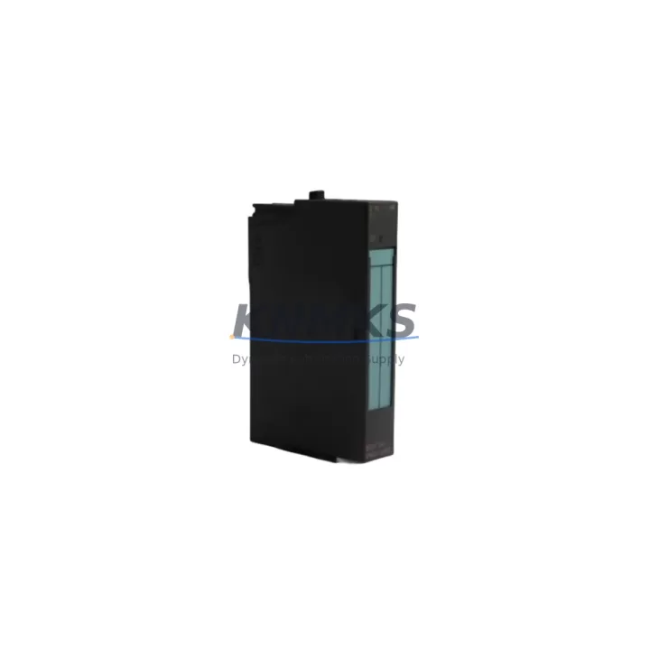
Overview
Siemens 6ES7870-1AA01-0YA1 Migration-Ready Modbus CP for S7-300: Legacy System Retrofit & Upgrade
The Siemens 6ES7870-1AA01-0YA1 is a Modbus Master Communications Processor designed for the SIMATIC S7-300 rack. As legacy S7-300 installations approach end-of-life and original Siemens supply channels become increasingly constrained, this module remains a critical spare part for plants that depend on Modbus RTU or Modbus ASCII serial communication links between PLCs, drives, meters, and field instruments. Whether you are managing a planned retrofit, responding to an unplanned failure, or building a strategic spare parts inventory to extend system life by 12 to 36 months, the 6ES7870-1AA01-0YA1 provides a direct, drop-in replacement path with no firmware re-engineering required on the S7-300 CPU side.
This module occupies a standard S7-300 signal module slot on the DIN-rail mounted rack and communicates with the CPU via the S7-300 backplane bus. It supports Modbus Master mode over RS-232 and RS-485 serial interfaces, making it compatible with a wide range of third-party field devices including variable frequency drives, intelligent motor controllers, energy meters, and remote I/O stations. When replacing a failed unit, engineers must verify the rack slot address assignment in the STEP 7 hardware configuration, confirm that the existing CP 340 or CP 341 configuration block (FB 7 / FC 7 driver) matches the replacement module’s firmware revision, and re-download the hardware configuration to the CPU before resuming production. In most cases, the original STEP 7 project can be reused without modification, which is a key advantage for minimizing downtime during unplanned outages.
For planned migration projects, the 6ES7870-1AA01-0YA1 is frequently used as an interim communications bridge while the broader control architecture is being upgraded from S7-300 to S7-1500 or ET 200SP-based distributed I/O. During this transition period, the Modbus CP continues to serve legacy field devices that have not yet been migrated to PROFINET or PROFIBUS DP, allowing the plant to phase the upgrade without a full production shutdown. Engineers should document the existing Modbus polling tables, baud rate settings, parity configuration, and slave address assignments before swapping the module, as these parameters must be re-entered in the STEP 7 CP configuration dialog. The RS-485 terminal wiring — typically on a 9-pin Sub-D connector or screw terminal adapter — should be verified against the original panel drawings to avoid signal polarity errors during commissioning.
In control cabinet upgrade scenarios where the S7-300 rack is being relocated or the cabinet layout is being redesigned, installation space must be confirmed before ordering. The 6ES7870-1AA01-0YA1 follows the standard S7-300 module form factor and requires a free slot adjacent to the CPU or an existing SM/CP module position. If the rack is fully populated, a rack expansion using an IM 360 / IM 361 interface module pair may be required to add capacity. Power budget calculations should also be reviewed: the S7-300 PS 307 power supply module must provide sufficient current on the 5 VDC backplane bus to support the additional CP load, particularly in high-density racks that already include multiple analog I/O modules and communication processors.
For sites running mixed communication architectures — for example, where some field devices use Modbus while others use PROFIBUS DP — the 6ES7870-1AA01-0YA1 can coexist in the same rack alongside a CP 342-5 PROFIBUS DP master module without conflict, as each CP occupies its own independent backplane slot and is addressed separately in the STEP 7 hardware configuration. This flexibility makes it well-suited for phased migration projects where not all field devices are being converted simultaneously. HMI screens built on SIMATIC WinCC or WinCC flexible that reference Modbus data tags via the S7-300 CPU’s data blocks will continue to function without modification, provided the data block structure and tag addresses are preserved during the CP replacement.
All units supplied by KNMKS undergo pre-shipment functional testing to verify backplane communication, serial port integrity, and module identification. Each unit is shipped with a support terms confirmed by quotation covering manufacturing defects and functional failures under normal operating conditions. Stock is maintained to support both single-unit emergency replacements and multi-unit bulk orders for spare parts programs. Global shipping is available with lead times confirmed at the time of order.
Migration Compatibility Table
| Parameter | Details |
|---|---|
| Module SKU | 6ES7870-1AA01-0YA1 |
| Compatible Rack | SIMATIC S7-300 standard rack (UR1, UR2) |
| Backplane Interface | S7-300 backplane bus (standard SM slot) |
| Communication Protocol | Modbus RTU / Modbus ASCII (Master mode) |
| Serial Interface | RS-232 / RS-485 (Sub-D 9-pin) |
| Replaces / Compatible With | CP 340 (6ES7340-1AH02-0AE0), CP 341 series |
| Programming Software | SIMATIC STEP 7 V5.x (FB 7 / FC 7 driver blocks) |
| Installation Requirement | Free S7-300 rack slot; verify power budget on PS 307 |
| Firmware Compatibility | Verify CP firmware version matches STEP 7 driver revision |
| HMI Compatibility | WinCC, WinCC flexible — no tag remapping required if DB structure preserved |
| Commissioning Steps | Re-download HW config; verify Modbus slave addresses and baud rate |
| Support terms | 12 months from shipment date |
| Pre-Shipment Test | Yes — backplane communication and serial port verified |
| Origin | Germany |
Retrofit Planning for Existing Automation Systems
A successful retrofit begins with a complete audit of the existing S7-300 rack configuration. Before ordering the 6ES7870-1AA01-0YA1, document the slot positions of all installed modules: the CPU 315-2 DP or CPU 317-2 PN/DP, any SM 321 digital input modules, SM 331 analog input modules, and existing CP modules. Confirm the rack type — UR1 (4-slot) or UR2 (9-slot) — and count available free slots. If the rack is fully populated, plan for an IM 360 expansion rack before the replacement unit arrives on site.
Power supply capacity is a common oversight in retrofit projects. The PS 307 5A or PS 307 10A power supply module must be checked against the total current draw of all installed modules on the 5 VDC backplane bus. Adding a communications processor increases the backplane load, and in high-density racks this can push the supply close to its rated limit. A current budget spreadsheet based on the module data sheets should be prepared before finalizing the rack layout.
For serial wiring, the RS-485 bus connecting the 6ES7870-1AA01-0YA1 to field devices such as Modbus-enabled variable frequency drives, energy meters, or remote terminal units must be verified for correct A/B polarity, termination resistor placement at both ends of the bus, and cable shielding continuity. In older installations, the original wiring may use non-standard color coding or may lack proper termination, both of which can cause intermittent communication errors after the module is replaced. A loop-back test using the CP’s diagnostic function in STEP 7 is recommended before connecting field devices.
When the retrofit also involves upgrading the HMI layer — for example, migrating from an older TP 177B touch panel to a current-generation KTP700 Basic panel — the WinCC flexible project must be reviewed to ensure that all Modbus data tags sourced from the S7-300 CPU’s data blocks remain correctly mapped. If the CPU program uses structured data blocks to buffer Modbus read data, the DB numbers and byte offsets must be consistent between the old and new CP configurations. This review should be completed in the engineering office before the on-site commissioning window begins, to avoid consuming field time on software corrections.
Downtime Control During System Migration
Minimizing production downtime during a CP replacement requires preparation at three levels: hardware staging, software verification, and on-site execution planning. At the hardware level, the replacement 6ES7870-1AA01-0YA1 should be bench-tested before the maintenance window using a spare S7-300 rack or a test rack if available. Confirm that the module is recognized by STEP 7 and that the CP configuration can be downloaded successfully. This eliminates the risk of receiving a non-functional unit during a live maintenance window.
At the software level, the existing STEP 7 project should be archived and backed up before any changes are made. The hardware configuration (HW Config) should be exported and stored alongside the project archive. If the replacement module has a different firmware version than the original, the corresponding FB 7 / FC 7 driver library version must be updated in the STEP 7 project before downloading. Failure to match the driver version to the firmware version is one of the most common causes of CP initialization errors after a module swap.
On-site, the replacement sequence should follow a defined procedure: power down the rack, remove the failed module, insert the replacement, power up, download the hardware configuration, verify the CP status LED sequence (RUN green, no SF red), and then execute a Modbus communication test to each slave device before handing the system back to operations. For critical production lines, a parallel hot-standby arrangement using a second S7-300 rack with a pre-configured CP can reduce the switchover time to under 15 minutes. Documenting the actual commissioning steps and any deviations from the planned procedure provides a valuable reference for future maintenance events and supports the support terms confirmed by quotation claim process if issues arise post-installation.
Retrofit Support FAQ
Q: Is the 6ES7870-1AA01-0YA1 a direct replacement for the CP 340 (6ES7340-1AH02-0AE0)?
A: The 6ES7870-1AA01-0YA1 and the CP 340 series both provide Modbus serial communication for the S7-300 rack, but they use different driver function blocks in STEP 7. Before swapping, verify which FB/FC driver version your existing program uses and confirm firmware compatibility. In most cases the Modbus polling logic and data block structure can be reused with minor configuration adjustments in HW Config.
Q: What baud rate and parity settings are supported, and how are they configured?
A: Baud rate, parity, stop bits, and Modbus mode (RTU or ASCII) are all configured in the STEP 7 HW Config CP properties dialog. Supported baud rates include 300 to 38400 bps on RS-232 and up to 38400 bps on RS-485. These settings must match the field device configuration exactly. After changing any serial parameters, a full hardware configuration download to the CPU is required.
Q: Does KNMKS provide pre-shipment testing, and what does the support terms confirmed by quotation cover?
A: Yes. Every unit is tested for backplane communication integrity and serial port functionality before dispatch. The support terms confirmed by quotation cover manufacturing defects and functional failures under normal operating conditions from the shipment date. Support requests are supported by our technical team at admin@knmks.com. Replacement or repair is arranged on a case-by-case basis with priority handling for production-critical applications.
Q: What is the typical lead time, and can bulk quantities be supplied for spare parts programs?
A: Stock availability is confirmed at the time of inquiry. Single units for emergency replacement are typically dispatched within 1–3 business days. Bulk orders for spare parts programs covering 12–36 months of planned consumption can be accommodated with scheduled delivery agreements. Contact admin@knmks.com or +86 18359268345 to discuss inventory reservation and pricing for multi-unit orders.
© 2026 KNMKS. All rights reserved.
Original Source: https://knmks.com
Contact: admin@knmks.com | +86 18359268345
Product Identification
- Brand / Ecosystem
-
Siemens
Siemens - Model / Series
-
6ES7870-1AA01-0YA1
SIMATIC Series - Product Family
- PLCs & Controllers
- Availability Status
- Available on request after model and quantity confirmation
- Inquiry Type
- B2B RFQ, replacement inquiry and project spare-part request
- Pre-Quote Check
- Exact SKU, brand, series, quantity, nameplate photos and destination country are checked before quotation
System Path
Where this product fits in the KNMKS automation structure.
Specification & Inquiry Focus
- Control platform
- PLC, PAC and modular controllers
- Common needs
- CPU, rack, power and I/O expansion
- Project support
- Replacement, cabinet build and maintenance
Buyer Confirmation
Information KNMKS checks before replying.
- Exact model
- 6ES7870-1AA01-0YA1
- Brand / ecosystem
- Siemens
- Product family
- PLCs & Controllers
- Application note
- Replacement, maintenance, project build or spare-part list
- Useful photos
- Nameplate, installed unit, cabinet layout or connector side
- Delivery details
- Quantity, destination country and target schedule
Document Support
Files and notes can be confirmed during quotation.
- Product photos or nameplate confirmation when available
- Packing and delivery notes before quotation confirmation
- Support scope and delivery terms confirmed per inquiry
- Export document coordination for qualified B2B requests
Inquiry Support
- Model cross-checking before quotation
- CPU, power, rack and expansion module matching
- Support for replacement and project inquiry
What to Send Us
- Brand and exact model number: Siemens 6ES7870-1AA01-0YA1
- Quantity and required delivery time
- Application, replacement requirement or nameplate photo
- Destination country and shipping preference
RFQ Preparation
This is a product inquiry page built for RFQ communication.
Fast Model Check
Send this model to KNMKS for confirmation.
Include quantity, destination country and photos if this is a maintenance replacement. The inquiry will be saved with a reference number after submission.
Brand & Compatibility Note
KNMKS displays automation product information for well-known industrial brand ecosystems and compatible replacement references. Brand names are used for product identification and compatibility reference only; final availability and commercial terms are confirmed per quotation.
 Manufacturing
 Machine Tools
 Packaging
 Energy & Power
 HMI & Displays
 Servo Systems
 Variable Frequency Drives
 Sensors