
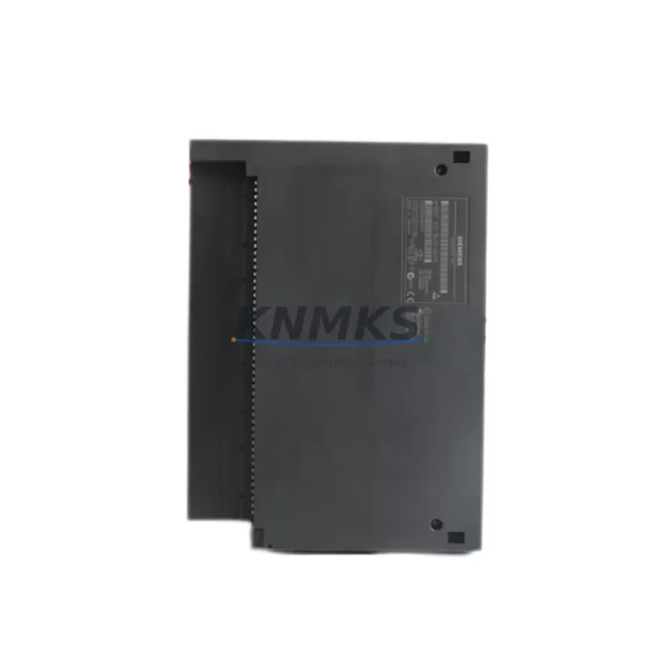
Overview
Siemens 6ES7422-1BL00-0AA0 Migration-Ready 32DO for Legacy Control Systems
The Siemens 6ES7422-1BL00-0AA0 is a 32-channel 24 VDC digital output module belonging to the SM422 signal module family, designed for integration into the Siemens S7-400 programmable logic controller platform. As legacy S7-400 installations approach end-of-life and original spare parts become increasingly scarce, the 6ES7422-1BL00-0AA0 serves as a verified drop-in replacement and migration-ready component for engineers undertaking control cabinet upgrades, production line retrofits, and system modernization projects.
This module mounts directly onto the S7-400 backplane rack — compatible with UR1, UR2, and ER1/ER2 expansion racks — and communicates via the internal P-bus and K-bus interfaces native to the S7-400 architecture. No additional interface adapters or bus couplers are required for standard rack installations, which significantly reduces retrofit complexity and minimizes the risk of wiring errors during changeover.
For facilities running aging S7-400 configurations alongside legacy HMI panels such as the OP7, OP17, or MP270, the 6ES7422-1BL00-0AA0 preserves existing I/O address mappings when installed in the same slot position as the original module. This means that STEP 7 hardware configuration files typically require only minor revision — or in many cases no modification at all — allowing engineers to protect original program logic, retain existing function block structures, and avoid costly reprogramming during planned maintenance windows.
Migration Compatibility Table
| Parameter | Detail |
|---|---|
| SKU / Order Number | 6ES7422-1BL00-0AA0 |
| Module Family | SM422 Digital Output |
| Compatible Platform | Siemens S7-400 (CPU 412, 414, 416, 417 series) |
| Output Channels | 32 × 24 VDC digital outputs |
| Output Current per Channel | 0.5 A (max) |
| Backplane Interface | S7-400 P-bus / K-bus (UR1, UR2, ER1, ER2 racks) |
| Terminal / Wiring | 40-pin front connector (6ES7492-1AL00-0AA0 compatible) |
| Power Supply Requirement | 24 VDC load voltage (external); backplane 5 VDC via rack |
| Slot Compatibility | Any signal module slot in S7-400 rack (slot 4 onward) |
| Firmware Compatibility | Compatible with STEP 7 V5.x and TIA Portal (via legacy mode) |
| Communication Protocol | S7-400 internal bus (no fieldbus adapter required) |
| Replacement Recommendation | Direct slot-for-slot replacement; verify front connector wiring before power-on |
| Commissioning Focus | I/O address confirmation, load voltage check, output diagnostics via CPU |
| Support terms | 12 months from date of shipment |
Retrofit Planning for Existing Automation Systems
Successful integration of the 6ES7422-1BL00-0AA0 into an existing S7-400 control system requires a structured pre-retrofit assessment. Engineers should begin by auditing the current rack configuration — documenting the PS407 or PS405 power supply module’s available current budget, since adding or replacing signal modules affects the total 5 VDC backplane load. The 6ES7422-1BL00-0AA0 draws approximately 100 mA from the backplane supply; confirm that the installed power supply module has sufficient headroom before proceeding.
Terminal wiring is a critical checkpoint. The module uses a 40-pin front connector, and existing field wiring from the legacy module should be transferred to the new connector using the original wiring diagram. If the original front connector (order number 6ES7492-1AL00-0AA0) is reused, verify that terminal screws are re-torqued to specification and that no conductors have been damaged during removal. For installations where the front connector is being replaced simultaneously, label all field cables before disconnection to prevent cross-wiring errors.
In systems where the S7-400 CPU communicates with remote I/O via PROFIBUS-DP — for example, using an ET 200M distributed I/O station with IM153-2 interface modules — the 6ES7422-1BL00-0AA0 installed in the central rack does not affect the PROFIBUS segment configuration. However, if the retrofit involves migrating from a central rack DO module to a distributed ET 200M configuration, engineers must update the PROFIBUS GSD file assignments and re-download the hardware configuration to the CPU.
For control cabinets that also house CP443-1 or CP443-5 communication processors for Industrial Ethernet or PROFIBUS network connectivity, confirm that the module replacement does not alter the rack slot assignments of these processors, as slot position changes can affect the CPU’s internal addressing and require a full hardware configuration reload. Similarly, if the cabinet includes a BM 393 bus module or IM460/IM461 interface modules for rack expansion, verify that the expansion bus remains intact and that no termination resistors have been disturbed during the retrofit procedure.
Where the existing system includes analog output modules such as the SM432 or additional digital input modules from the SM421 family installed in adjacent slots, ensure that the physical installation of the 6ES7422-1BL00-0AA0 does not apply lateral stress to neighboring module connectors. S7-400 modules are secured with top and bottom locking levers; confirm both levers are fully engaged after installation before applying power.
Downtime Control During System Migration
Minimizing unplanned downtime is the primary operational concern during any live-system module replacement. For the 6ES7422-1BL00-0AA0, the recommended approach is to perform the swap during a scheduled maintenance window with the S7-400 CPU placed in STOP mode. Before initiating the replacement, upload the current CPU program — including all data blocks, organization blocks, and system function blocks — to a programming device running STEP 7 or TIA Portal in legacy compatibility mode. This ensures that a verified program backup exists independently of the CPU’s internal memory.
Once the CPU is in STOP mode and the rack power supply has been de-energized, the original DO module can be removed and the 6ES7422-1BL00-0AA0 installed in the same slot. If the front connector wiring has been pre-transferred to a new connector, installation time is typically under ten minutes. After re-energizing the rack, the CPU should be returned to RUN mode and output diagnostics verified via the STEP 7 hardware diagnostics tool or the CPU’s integrated display. Check that all 32 output channels report no fault conditions before releasing the system to production.
For facilities where continuous operation is required and a brief controlled shutdown is not feasible, consider staging a parallel test rack with the 6ES7422-1BL00-0AA0 pre-configured and verified offline before the live swap. This approach allows the replacement module to be fully tested — including output load verification and firmware compatibility confirmation — without impacting the running process. Shipment testing is performed on all units prior to dispatch, and each module is supplied with a test report confirming channel-level output verification.
All units are supplied from verified inventory with a support terms confirmed by quotation covering manufacturing defects and functional failures under normal operating conditions. Stock availability is confirmed at time of order, and expedited dispatch is available for urgent retrofit and breakdown recovery requirements.
Retrofit Support FAQ
Q: Is the 6ES7422-1BL00-0AA0 a direct replacement for other SM422 variants such as the 6ES7422-1HH00-0AA0?
A: The 6ES7422-1BL00-0AA0 (32 × 24 VDC outputs, 0.5 A per channel) and the 6ES7422-1HH00-0AA0 (16 × 120/230 VAC outputs) are both SM422 family modules but have different output voltage ratings and channel counts. They are not electrically interchangeable. Confirm the output voltage and current requirements of your field devices before selecting a replacement module. For 24 VDC output applications with 32 channels, the 6ES7422-1BL00-0AA0 is the correct selection.
Q: Do I need to modify my STEP 7 hardware configuration after installing the 6ES7422-1BL00-0AA0 in the same slot as the original module?
A: If the replacement module is installed in the same rack slot as the original 6ES7422-1BL00-0AA0, no hardware configuration changes are required. The CPU will recognize the module at the same I/O address range. If the module is installed in a different slot, the hardware configuration must be updated in STEP 7 or TIA Portal and re-downloaded to the CPU before returning to RUN mode.
Q: What commissioning checks should be performed after installation?
A: After installation and power-up, verify the following: (1) No SF (system fault) LED on the module or CPU; (2) All 32 output channels respond correctly to test signals issued from the programming device; (3) Load voltage (24 VDC) is present at the front connector terminals; (4) No diagnostic messages appear in the STEP 7 hardware diagnostics buffer. If any channel reports a fault, check the corresponding field wiring for short circuits or open loads before concluding that the module is defective.
Q: What support terms and supply conditions apply to this module?
A: All units are supplied with a support terms confirmed by quotation from the date of shipment, covering manufacturing defects and functional failures under normal operating conditions. Each unit undergoes shipment testing prior to dispatch. Stock availability is confirmed at order placement, and expedited shipping is available for breakdown and urgent retrofit requirements. Contact our sales team for lead time and inventory confirmation.
© 2026 KNMKS. All rights reserved.
Original Source: https://knmks.com
Contact: admin@knmks.com | +86 18359268345
Product Identification
- Brand / Ecosystem
-
Siemens
Siemens - Model / Series
-
6ES7422-1BL00-0AA0
SIMATIC Series - Product Family
- PLCs & Controllers
- Availability Status
- Available on request after model and quantity confirmation
- Inquiry Type
- B2B RFQ, replacement inquiry and project spare-part request
- Pre-Quote Check
- Exact SKU, brand, series, quantity, nameplate photos and destination country are checked before quotation
System Path
Where this product fits in the KNMKS automation structure.
Specification & Inquiry Focus
- Control platform
- PLC, PAC and modular controllers
- Common needs
- CPU, rack, power and I/O expansion
- Project support
- Replacement, cabinet build and maintenance
Buyer Confirmation
Information KNMKS checks before replying.
- Exact model
- 6ES7422-1BL00-0AA0
- Brand / ecosystem
- Siemens
- Product family
- PLCs & Controllers
- Application note
- Replacement, maintenance, project build or spare-part list
- Useful photos
- Nameplate, installed unit, cabinet layout or connector side
- Delivery details
- Quantity, destination country and target schedule
Document Support
Files and notes can be confirmed during quotation.
- Product photos or nameplate confirmation when available
- Packing and delivery notes before quotation confirmation
- Support scope and delivery terms confirmed per inquiry
- Export document coordination for qualified B2B requests
Inquiry Support
- Model cross-checking before quotation
- CPU, power, rack and expansion module matching
- Support for replacement and project inquiry
What to Send Us
- Brand and exact model number: Siemens 6ES7422-1BL00-0AA0
- Quantity and required delivery time
- Application, replacement requirement or nameplate photo
- Destination country and shipping preference
RFQ Preparation
This is a product inquiry page built for RFQ communication.
Fast Model Check
Send this model to KNMKS for confirmation.
Include quantity, destination country and photos if this is a maintenance replacement. The inquiry will be saved with a reference number after submission.
Brand & Compatibility Note
KNMKS displays automation product information for well-known industrial brand ecosystems and compatible replacement references. Brand names are used for product identification and compatibility reference only; final availability and commercial terms are confirmed per quotation.
 Manufacturing
 Machine Tools
 Packaging
 Energy & Power
 HMI & Displays
 Servo Systems
 Variable Frequency Drives
 Sensors