
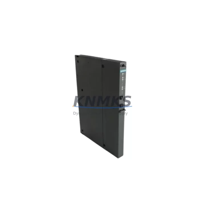
Overview
Siemens 6ES7407-0DA02-0AA0 Migration-Ready PS407: Legacy System Migration and Compatible Upgrade
The Siemens 6ES7407-0DA02-0AA0 is a PS407 4A power supply module designed for the SIMATIC S7-400 programmable logic controller platform. As legacy S7-400 installations approach end-of-life and original Siemens spare parts become increasingly difficult to source, this migration-ready replacement module provides a direct, wiring-compatible solution for maintenance engineers, system integrators, and plant automation teams managing aging control infrastructure.
Whether you are replacing a failed unit in a running production line, planning a phased control cabinet upgrade, or executing a full PLC platform migration, the 6ES7407-0DA02-0AA0 is engineered to slot into existing S7-400 rack configurations without requiring backplane modifications. The module delivers a regulated 24 VDC output at 4A continuous load, supporting the power budget requirements of standard S7-400 central racks populated with CPU modules such as the 6ES7414 or 6ES7416 series, digital I/O modules, and communication processors.
Before installation, engineers should verify the total current draw of all installed modules against the 4A output rating. In high-density racks carrying analog input modules, PROFIBUS DP communication modules such as the CP 443-1, or additional interface modules for distributed I/O expansion via ET 200M remote stations, a higher-capacity supply such as the PS407 10A (6ES7407-0KA02-0AA0) may be required. Confirming the rack’s power budget prior to commissioning eliminates the risk of undervoltage faults during startup.
Terminal wiring on the 6ES7407-0DA02-0AA0 follows the standard S7-400 power supply pinout, accepting 120/230 VAC input with automatic range selection. Existing field wiring from the original supply can be reconnected directly without rewiring the control cabinet, significantly reducing installation time and the risk of wiring errors during a live system changeover. The module’s front panel LED indicators for DC OK and group fault status are compatible with existing HMI alarm mapping on SIMATIC WinCC or WinCC flexible panels, so no HMI screen modifications are required for basic status monitoring.
For sites running STEP 7 V5.x projects, no program changes are required when replacing the power supply module. The CPU retains its configuration in the hardware catalog, and the power supply slot assignment does not affect the CPU’s module addressing or I/O mapping. Engineers performing the swap should note the CPU’s current operating mode, back up the project to a PG/PC via a standard MPI/PROFIBUS programming cable or SIMATIC NET CP, and confirm that the CPU returns to RUN mode after the replacement without requiring a memory reset. If the installation includes a redundant CPU configuration using the H-system architecture, the standby CPU should be verified as active before the primary rack power supply is replaced.
In retrofit scenarios where the S7-400 rack is being partially upgraded — for example, replacing legacy S5-compatible interface modules with current ET 200S or ET 200SP distributed I/O nodes — the power supply’s output capacity should be recalculated to account for any new modules added to the central rack. Distributed I/O nodes connected via PROFIBUS DP or PROFINET draw their own field power independently, but any new IM (interface module) installed in the central rack will contribute to the rack’s internal 5 VDC bus load, which is supplied by the PS407.
KNMKS maintains stock of the 6ES7407-0DA02-0AA0 for immediate dispatch, supporting urgent breakdown maintenance and planned shutdown windows. Each unit is pre-shipment tested and supplied with a support terms confirmed by quotation covering manufacturing defects and functional performance. Lead times for in-stock units are typically 2–5 business days for international shipments.
Migration Compatibility Table
| Parameter | Details |
|---|---|
| SKU / Part Number | 6ES7407-0DA02-0AA0 |
| Module Type | PS407 4A Power Supply Module |
| Compatible Platform | SIMATIC S7-400 (all standard rack configurations) |
| Output Voltage / Current | 24 VDC / 4A continuous |
| Input Voltage | 120 / 230 VAC (auto-range) |
| Backplane Interface | S7-400 standard backplane bus connector |
| Installation Slot | Slot 1 (leftmost position) of S7-400 central rack (UR1, UR2) |
| Wiring Compatibility | Direct replacement — existing AC input wiring reusable |
| Communication Impact | None — CPU retains program and configuration after swap |
| HMI Screen Changes Required | None for standard DC OK / fault status monitoring |
| Firmware Compatibility | Compatible with all S7-400 CPU firmware versions |
| Replacement Recommendation | Direct drop-in for failed or end-of-life PS407 4A units |
| Upgrade Path | If rack load exceeds 4A, upgrade to 6ES7407-0KA02-0AA0 (10A) |
| Pre-Shipment Testing | Yes — functional output and load test performed |
| Support terms | 12 Months from date of shipment |
| Origin | Germany |
| Stock Status | Available — contact KNMKS for lead time confirmation |
Retrofit Planning for Existing Automation Systems
Replacing the 6ES7407-0DA02-0AA0 in an operational S7-400 system requires a structured approach to avoid unplanned downtime and configuration errors. The following planning checklist covers the key technical checkpoints that field engineers should address before and during the replacement.
Power Budget Verification: Calculate the total 5 VDC and 24 VDC current consumption of all modules installed in the rack. The PS407 4A supplies both the internal 5 VDC backplane bus and the 24 VDC load current. If the rack contains a high count of analog I/O modules — for example, SM 431 analog input modules or SM 432 analog output modules — or if a CP 443-5 PROFIBUS communication processor is installed, the aggregate load may approach or exceed the 4A rating. In such cases, consider replacing with the higher-capacity PS407 10A variant.
Backplane and Rack Inspection: Inspect the S7-400 rack’s backplane connector for corrosion, bent pins, or mechanical damage before installing the replacement module. The UR1 and UR2 universal racks use the same backplane bus standard, so the 6ES7407-0DA02-0AA0 is compatible with both. If the rack itself is being replaced as part of a broader cabinet upgrade, ensure the new rack’s slot count accommodates all existing CPU, I/O, and communication modules without requiring additional expansion racks connected via IM 460/461 interface modules.
CPU and Program Backup: Before removing the existing power supply, connect a programming device running STEP 7 or TIA Portal (in S7-400 compatibility mode) via an MPI adapter or PROFIBUS programming cable and perform a full project upload. Store the backup on a secure network location. This ensures that if the CPU’s battery-backed RAM loses its program during the power interruption, the project can be reloaded immediately without searching for the original engineering station.
HMI and SCADA Continuity: If the S7-400 CPU communicates with a SIMATIC Panel PC or a WinCC SCADA server via Industrial Ethernet using a CP 443-1 communication module, the HMI connection will be interrupted during the power supply swap. Notify the control room operator in advance and, where possible, schedule the replacement during a planned maintenance window. After power restoration, verify that the CP 443-1 re-establishes its Ethernet connection and that all WinCC tags resume updating within the expected scan cycle.
Distributed I/O Reconnection: If the S7-400 system controls remote ET 200M or ET 200S distributed I/O stations via PROFIBUS DP, the DP master (typically the CPU’s integrated DP port or a CP 342-5 communication module) will re-initialize the PROFIBUS network after power restoration. Confirm that all remote stations return to DATA_EXCHANGE state and that no DP slave addresses have been lost. This is particularly important in installations where the PROFIBUS segment includes third-party devices such as variable frequency drives or remote I/O nodes from other manufacturers.
Downtime Control During System Migration
Minimizing control system downtime during a power supply replacement requires preparation, clear communication with operations, and a defined rollback plan. The following practices are recommended for the 6ES7407-0DA02-0AA0 replacement in a live production environment.
Pre-Staging: Unbox and inspect the replacement module before the maintenance window begins. Verify the module’s output voltage using a calibrated multimeter on the bench before installation. This eliminates the risk of discovering a transit-damaged unit after the original supply has already been removed from the rack.
Controlled Shutdown Sequence: Where the process allows, bring the controlled equipment to a safe state before removing power from the S7-400 rack. For continuous process applications — such as conveyor systems, pump stations, or temperature-controlled chambers — coordinate with the process engineer to identify a safe hold point. Document the current setpoints and output states so that the process can be restarted from a known condition after the replacement.
Program Logic Preservation: The S7-400 CPU stores its operating program in battery-backed RAM and, optionally, on a memory card (MC). If the CPU is equipped with a memory card containing the project, the program will be automatically reloaded from the card after power restoration, eliminating the risk of program loss even if the backup battery is depleted. Verify the memory card status in STEP 7’s hardware configuration before the maintenance window.
Post-Replacement Verification: After installing the 6ES7407-0DA02-0AA0 and restoring power, confirm the following in sequence: DC OK LED illuminated on the power supply front panel; CPU transitions to RUN mode without fault; all I/O modules show green status LEDs; PROFIBUS DP network returns to DATA_EXCHANGE; HMI tags resume updating; and process outputs respond correctly to manual test commands. Document the completion time and any anomalies observed for the maintenance record.
Spare Unit Retention: Given the extended lifecycle of S7-400 installations — many of which remain in service 15–20 years beyond the platform’s original release — maintaining a spare 6ES7407-0DA02-0AA0 on-site is strongly recommended. KNMKS supports long-term spare parts supply agreements for the PS407 series, with inventory commitments available for 12–36 month horizons to support multi-site maintenance programs.
Retrofit Support FAQ
Q: Is the 6ES7407-0DA02-0AA0 a direct replacement for the earlier 6ES7407-0DA01-0AA0 revision?
A: Yes. The -0DA02- revision is the current production revision of the PS407 4A module and is backward-compatible with the -0DA01- revision in all standard S7-400 rack configurations. No hardware or software changes are required when upgrading from the earlier revision.
Q: Will the CPU lose its program when the power supply is replaced?
A: If the CPU is equipped with a charged backup battery and a memory card, the program is retained in battery-backed RAM and reloaded from the memory card on power-up. As a precaution, KNMKS recommends performing a full project backup via STEP 7 or TIA Portal before any power interruption. Each 6ES7407-0DA02-0AA0 supplied by KNMKS is pre-shipment tested to confirm correct output voltage and load regulation before dispatch.
Q: Can this module be used in an S7-400H redundant system?
A: The 6ES7407-0DA02-0AA0 is compatible with standard S7-400 racks used in H-system configurations. In a redundant setup, each rack has its own power supply. The replacement procedure should be performed on one rack at a time, with the redundant CPU confirmed as active before the primary rack supply is removed.
Q: What support terms and supply terms does KNMKS offer for this module?
A: All 6ES7407-0DA02-0AA0 units supplied by KNMKS carry a support terms confirmed by quotation from the date of shipment, covering manufacturing defects and functional performance. KNMKS maintains stock for immediate dispatch and can support long-term supply agreements for maintenance programs requiring guaranteed inventory over 12–36 month periods. Contact admin@knmks.com for volume pricing and supply commitment terms.
© 2026 KNMKS. All rights reserved.
Original Source: https://knmks.com
Contact: admin@knmks.com | +86 18359268345
Product Identification
- Brand / Ecosystem
-
Siemens
Siemens - Model / Series
-
6ES7407-0DA02-0AA0
SIMATIC Series - Product Family
- PLCs & Controllers
- Availability Status
- Available on request after model and quantity confirmation
- Inquiry Type
- B2B RFQ, replacement inquiry and project spare-part request
- Pre-Quote Check
- Exact SKU, brand, series, quantity, nameplate photos and destination country are checked before quotation
System Path
Where this product fits in the KNMKS automation structure.
Specification & Inquiry Focus
- Control platform
- PLC, PAC and modular controllers
- Common needs
- CPU, rack, power and I/O expansion
- Project support
- Replacement, cabinet build and maintenance
Buyer Confirmation
Information KNMKS checks before replying.
- Exact model
- 6ES7407-0DA02-0AA0
- Brand / ecosystem
- Siemens
- Product family
- PLCs & Controllers
- Application note
- Replacement, maintenance, project build or spare-part list
- Useful photos
- Nameplate, installed unit, cabinet layout or connector side
- Delivery details
- Quantity, destination country and target schedule
Document Support
Files and notes can be confirmed during quotation.
- Product photos or nameplate confirmation when available
- Packing and delivery notes before quotation confirmation
- Support scope and delivery terms confirmed per inquiry
- Export document coordination for qualified B2B requests
Inquiry Support
- Model cross-checking before quotation
- CPU, power, rack and expansion module matching
- Support for replacement and project inquiry
What to Send Us
- Brand and exact model number: Siemens 6ES7407-0DA02-0AA0
- Quantity and required delivery time
- Application, replacement requirement or nameplate photo
- Destination country and shipping preference
RFQ Preparation
This is a product inquiry page built for RFQ communication.
Fast Model Check
Send this model to KNMKS for confirmation.
Include quantity, destination country and photos if this is a maintenance replacement. The inquiry will be saved with a reference number after submission.
Brand & Compatibility Note
KNMKS displays automation product information for well-known industrial brand ecosystems and compatible replacement references. Brand names are used for product identification and compatibility reference only; final availability and commercial terms are confirmed per quotation.
 Manufacturing
 Machine Tools
 Packaging
 Energy & Power
 HMI & Displays
 Servo Systems
 Variable Frequency Drives
 Sensors