
Overview
Siemens 6ES7400-2JA10-0AA1 Migration-Ready CPU for Legacy S7-400 Systems
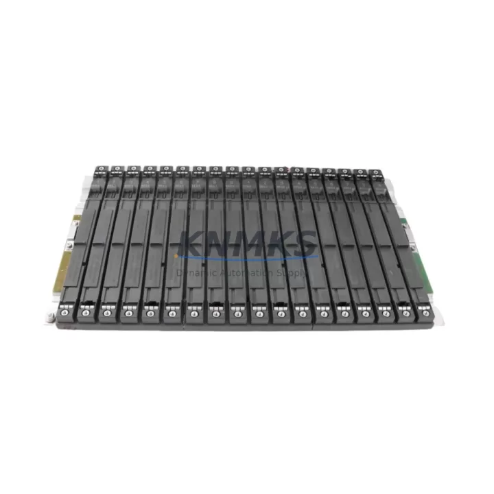
The Siemens 6ES7400-2JA10-0AA1 is a high-performance central processing unit designed for the SIMATIC S7-400 programmable logic controller platform. As legacy S7-400 installations approach end-of-life and spare parts become increasingly difficult to source, the 6ES7400-2JA10-0AA1 serves as a proven migration-ready replacement for discontinued CPU variants across the S7-400 family. Whether you are managing a scheduled control cabinet upgrade, responding to an unplanned CPU failure, or executing a phased DCS-to-PLC migration, this module provides the processing headroom, communication flexibility, and backward compatibility required to restore and sustain production continuity.
This CPU supports both PROFIBUS-DP and MPI communication protocols natively, making it directly compatible with existing field device networks, distributed I/O racks, and HMI connections without requiring protocol converters or gateway hardware. Engineers migrating from earlier S7-400 CPU variants — including the 6ES7400-1JA11-0AA0 and 6ES7400-2JA00-0AA0 — will find that the 6ES7400-2JA10-0AA1 retains the same CR2 and UR2 rack slot footprint, preserving existing backplane wiring and module addressing schemes. This significantly reduces the scope of hardware rework during a retrofit and allows the original STEP 7 program logic to be reloaded with minimal modification.
Before committing to a CPU swap in a live production environment, retrofit engineers should verify several critical compatibility parameters. Power supply capacity is the first checkpoint: confirm that the installed PS 407 power supply module — typically a 6ES7407-0DA02-0AA0 or 6ES7407-0KA02-0AA0 — can sustain the current draw of the replacement CPU alongside all installed I/O and communication modules. Backplane interface compatibility must also be confirmed; the 6ES7400-2JA10-0AA1 is designed for the S7-400 UR1 and UR2 universal racks and is not interchangeable with S7-300 or S7-200 backplane architectures. Module slot addressing should be reviewed in the hardware configuration (HW Config) within STEP 7 or TIA Portal to ensure the CPU slot assignment and I/O module addresses are preserved after the swap. Any mismatch in the hardware configuration will prevent the CPU from entering RUN mode and may trigger a STOP fault on startup.
Communication link integrity is another area requiring careful pre-migration validation. If the existing installation uses a CP 443-1 Ethernet communication processor (such as the 6GK7443-1EX30-0XE0) for SCADA connectivity or remote programming access, verify that the firmware version on the CP module is compatible with the replacement CPU’s operating system version. Similarly, if the control system includes a FM 455 closed-loop control module or a SM 421 digital input module in the same rack, confirm that the module parameters stored in the CPU’s load memory are intact and will be correctly recognized after the CPU replacement. Retaining the original MMC (Micro Memory Card) from the failed CPU — or transferring the program to a new card using a PG/PC with STEP 7 — is the recommended approach to preserve program logic, data blocks, and hardware configuration data.
HMI screen integrity is frequently overlooked during CPU migrations. If the plant uses a SIMATIC Panel PC or a TP/OP series operator panel connected via MPI or PROFIBUS, verify that the HMI project’s PLC connection parameters — including the MPI address, baud rate, and slot number — match the replacement CPU’s configuration. A mismatch here will result in communication timeouts on the HMI and may require a partial HMI project update before the system can be returned to normal operation.
Installation space confirmation is straightforward for this CPU: the 6ES7400-2JA10-0AA1 occupies a single slot in the S7-400 rack and does not require additional mounting hardware. However, engineers should verify that the control cabinet has adequate ventilation clearance above and below the rack, particularly in high-ambient-temperature environments where thermal derating may affect CPU performance. Firmware version compatibility should also be checked if the installation includes any intelligent modules — such as a CP 443-5 PROFIBUS communication processor — that communicate directly with the CPU via the backplane bus.
Migration Compatibility Table
| Parameter | Details |
|---|---|
| SKU / Part Number | 6ES7400-2JA10-0AA1 |
| Compatible Rack | S7-400 UR1, UR2 Universal Racks |
| Communication Interfaces | MPI, PROFIBUS-DP (integrated) |
| Replaces / Supersedes | 6ES7400-1JA11-0AA0, 6ES7400-2JA00-0AA0 and compatible S7-400 CPU variants |
| Programming Software | SIMATIC STEP 7 V5.x, TIA Portal (via legacy support) |
| Backplane Bus | S7-400 P-bus / K-bus (not compatible with S7-300 or S7-200 racks) |
| Power Supply Compatibility | PS 407 series (5 A / 10 A variants); verify total rack current budget |
| Memory Card | Siemens MMC (Micro Memory Card); program transfer via PG/PC recommended |
| Installation Slot | Single slot; no additional mounting hardware required |
| Commissioning Tool | SIMATIC STEP 7 HW Config; MPI/PROFIBUS programming cable required |
| Pre-shipment Testing | Full functional test performed; power-on and communication verification included |
| Support terms | support terms confirmed by quotation — covers manufacturing defects and functional failures |
Retrofit Planning for Existing Automation Systems
A successful S7-400 CPU retrofit begins well before the replacement module arrives on site. The first step is a complete rack audit: document every module installed in the UR1 or UR2 rack, including slot positions, module order numbers, and firmware versions. Pay particular attention to any SM 422 digital output modules or SM 431 analog input modules that may have module-specific parameters stored in the CPU’s load memory — these parameters must be backed up before the CPU is removed. If the rack includes an IM 460 send interface module for expansion rack connectivity, verify that the expansion rack configuration is correctly reflected in the STEP 7 hardware configuration before proceeding.
Terminal wiring on the CPU itself is limited to the MPI/PROFIBUS port connections and the power supply interface — both of which use standard S7-400 connectors and do not require rewiring when replacing a like-for-like CPU variant. However, if the retrofit involves upgrading from an older CPU with a single MPI port to the 6ES7400-2JA10-0AA1’s dual-port configuration, plan for the additional PROFIBUS segment connection and ensure the network topology is updated in the STEP 7 project accordingly.
For plants running mixed communication architectures — for example, a PROFIBUS field network for distributed I/O alongside an MPI link to a SIMATIC WinCC SCADA station — the retrofit plan should include a communication link verification step after CPU replacement. This involves confirming that all PROFIBUS slave addresses are correctly recognized by the new CPU and that the WinCC OPC server or S7 channel connection re-establishes without manual intervention. If the installation uses a CP 443-1 Advanced Ethernet module for S7 communication over TCP/IP, update the CP module’s configuration in STEP 7 to reference the replacement CPU’s slot number if it has changed.
Downtime Control During System Migration
Minimizing unplanned downtime during a CPU replacement requires a structured pre-migration checklist and a clear rollback plan. Before removing the existing CPU, perform a full online backup of the STEP 7 project — including all program blocks (OB, FB, FC, DB), the hardware configuration, and any force tables or variable tables in use. Store this backup on a PG/PC that will be available on-site during the migration window. If the plant operates on a 24/7 production schedule, coordinate the CPU swap during a planned maintenance window and notify all operators of the expected control system interruption.
To protect original program logic, avoid making any changes to the STEP 7 project between the backup and the CPU replacement. After installing the 6ES7400-2JA10-0AA1, load the backed-up hardware configuration first, then download the program blocks. This sequence ensures that the CPU’s module parameters are correctly initialized before the program begins executing. If the CPU enters STOP mode after the first download, check the diagnostic buffer in STEP 7 for configuration mismatches — common causes include incorrect rack/slot assignments for I/O modules or missing module parameters for intelligent modules.
Field control continuity can be maintained during the CPU swap by placing all output modules in a safe state before removing the CPU. Most S7-400 SM 422 digital output modules support a configurable substitute value behavior that holds outputs at a defined safe state when the CPU is in STOP or removed from the rack. Verify that substitute values are correctly configured for all safety-critical outputs before beginning the swap. After the replacement CPU is installed and the program is running, perform a structured I/O verification test — cycling each output and confirming each input — before returning the system to automatic mode.
Retrofit Support FAQ
Q1: Is the 6ES7400-2JA10-0AA1 a direct drop-in replacement for the 6ES7400-2JA00-0AA0?
In most installations, yes. Both CPUs share the same S7-400 rack slot footprint and support MPI and PROFIBUS-DP communication. However, you should verify the hardware configuration in STEP 7 and update the CPU order number in HW Config before downloading to the replacement module. Minor firmware differences may require a STEP 7 version check before the download is accepted.
Q2: What commissioning steps are required after installing the replacement CPU?
After physical installation, connect a PG/PC via MPI or PROFIBUS programming cable, load the hardware configuration, download the program blocks, and perform a full I/O verification test. Check the CPU diagnostic buffer for any startup faults and confirm that all communication modules — including CP 443-1 or CP 443-5 variants — have re-established their connections. HMI communication should be verified last, as operator panels may require a manual reconnection after the CPU restart.
Q3: How is the module tested before shipment?
Every 6ES7400-2JA10-0AA1 unit undergoes a full functional test prior to shipment, including power-on verification, communication port testing, and a visual inspection for physical damage. Units are shipped in anti-static packaging with protective covers on all connectors. A test report is available upon request for quality-critical applications.
Q4: What does the support terms confirmed by quotation cover, and what is the stock availability?
The support terms confirmed by quotation cover manufacturing defects and functional failures under normal operating conditions. It does not cover damage caused by incorrect installation, overvoltage, or environmental factors outside the module’s rated specifications. Stock is maintained in regional warehouses to support global delivery details confirmed by RFQ — typical lead time is 3–7 business days depending on destination. Contact admin@knmks.com or +86 18359268345 for real-time stock confirmation and bulk order pricing.
© 2026 KNMKS. All rights reserved.
Original Source: https://knmks.com
Contact: admin@knmks.com | +86 18359268345
Product Identification
- Brand / Ecosystem
-
Siemens
Siemens - Model / Series
-
6ES7400-2JA10-0AA1
SIMATIC Series - Product Family
- PLCs & Controllers
- Availability Status
- Available on request after model and quantity confirmation
- Inquiry Type
- B2B RFQ, replacement inquiry and project spare-part request
- Pre-Quote Check
- Exact SKU, brand, series, quantity, nameplate photos and destination country are checked before quotation
System Path
Where this product fits in the KNMKS automation structure.
Specification & Inquiry Focus
- Control platform
- PLC, PAC and modular controllers
- Common needs
- CPU, rack, power and I/O expansion
- Project support
- Replacement, cabinet build and maintenance
Buyer Confirmation
Information KNMKS checks before replying.
- Exact model
- 6ES7400-2JA10-0AA1
- Brand / ecosystem
- Siemens
- Product family
- PLCs & Controllers
- Application note
- Replacement, maintenance, project build or spare-part list
- Useful photos
- Nameplate, installed unit, cabinet layout or connector side
- Delivery details
- Quantity, destination country and target schedule
Document Support
Files and notes can be confirmed during quotation.
- Product photos or nameplate confirmation when available
- Packing and delivery notes before quotation confirmation
- Support scope and delivery terms confirmed per inquiry
- Export document coordination for qualified B2B requests
Inquiry Support
- Model cross-checking before quotation
- CPU, power, rack and expansion module matching
- Support for replacement and project inquiry
What to Send Us
- Brand and exact model number: Siemens 6ES7400-2JA10-0AA1
- Quantity and required delivery time
- Application, replacement requirement or nameplate photo
- Destination country and shipping preference
RFQ Preparation
This is a product inquiry page built for RFQ communication.
Fast Model Check
Send this model to KNMKS for confirmation.
Include quantity, destination country and photos if this is a maintenance replacement. The inquiry will be saved with a reference number after submission.
Brand & Compatibility Note
KNMKS displays automation product information for well-known industrial brand ecosystems and compatible replacement references. Brand names are used for product identification and compatibility reference only; final availability and commercial terms are confirmed per quotation.
 Manufacturing
 Machine Tools
 Packaging
 Energy & Power
 HMI & Displays
 Servo Systems
 Variable Frequency Drives
 Sensors