
Overview
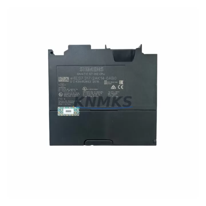
Siemens 6ES7317-2AK14-0AB0 Migration-Ready CPU for Legacy Control Systems
The Siemens 6ES7317-2AK14-0AB0 (CPU317-2 DP) is a high-performance central processing unit from the SIMATIC S7-300 series, purpose-built for demanding industrial automation environments. As legacy S7-300 installations approach end-of-life and original CPU modules become increasingly difficult to source, the 6ES7317-2AK14-0AB0 serves as a direct, migration-ready replacement that preserves existing program logic, field wiring, and communication architecture without requiring a full platform overhaul.
This CPU is widely deployed in process control, discrete manufacturing, material handling, and utility automation. Its dual-port PROFIBUS DP interface and integrated MPI port make it a natural fit for facilities running mixed communication topologies — particularly those migrating from earlier CPU315-2 DP or CPU316-2 DP variants where the backplane pinout and rack addressing remain compatible. Engineers undertaking a like-for-like swap must verify the firmware version loaded on the replacement unit against the STEP 7 project file; mismatched firmware revisions can prevent successful program download or cause unexpected OB fault behavior during first power-up.
Before committing to a retrofit, the following pre-installation checklist is strongly recommended:
- Power supply capacity: Confirm the existing PS 307 or PS 305 power supply (e.g., 6ES7307-1EA01-0AA0 or 6ES7307-1KA02-0AA0) can sustain the current draw of the replacement CPU plus all installed I/O modules. The 6ES7317-2AK14-0AB0 draws up to 800 mA from the 5 V backplane bus; total rack current budget must be recalculated if additional SM modules have been added since the original design.
- Backplane and rack compatibility: The module slots into any standard S7-300 rail (e.g., 6ES7390-1AE80-0AA0 or 6ES7390-1AF30-0AA0). Verify that the rack is not a compact S7-300 variant, which uses a different bus connector geometry.
- Module addressing: Slot addresses assigned in the original hardware configuration (HW Config) must be preserved. If the replacement CPU is installed in a different physical slot position, the I/O address map will shift and require a full HW Config rebuild and download.
- Terminal wiring: No field wiring changes are required for a direct CPU swap. Signal modules (SM 321, SM 322, SM 331, SM 332) remain in place. However, if the retrofit includes adding an SM 374 simulation module or a CP 343-1 Ethernet communication processor for protocol migration, terminal assignments on adjacent modules must be documented before any physical work begins.
- HMI screen compatibility: WinCC flexible or WinCC Runtime projects connected via MPI or PROFIBUS must be re-tested after the CPU swap. Tag addresses are preserved if the DB and variable structure in the STEP 7 project is unchanged, but communication parameters (station address, baud rate) should be confirmed against the HMI project settings.
- Program backup: Upload the existing program from the installed CPU before removal. Store the AWL/STL source, symbol table, and hardware configuration as a versioned archive. This protects against data loss if the original CPU fails during the removal process.
Migration Compatibility Table
| Parameter | 6ES7317-2AK14-0AB0 (This Unit) | Typical Legacy Predecessor | Retrofit Notes |
|---|---|---|---|
| CPU Series | SIMATIC S7-300, CPU317-2 DP | CPU315-2 DP / CPU316-2 DP | Direct rack-compatible replacement; verify slot position |
| Communication Ports | MPI + PROFIBUS DP (Master/Slave) | MPI + PROFIBUS DP | Station addresses must match original configuration |
| Work Memory | 512 KB (expandable via MMC) | 128–256 KB | Larger memory supports expanded program blocks without restructuring |
| Backplane Interface | Standard S7-300 bus connector | Standard S7-300 bus connector | No mechanical modification required |
| Power Consumption (5V bus) | 800 mA | 500–700 mA | Recalculate PS capacity before installation |
| Programming Software | STEP 7 V5.5 SP4 or higher | STEP 7 V5.x | Confirm firmware compatibility with installed STEP 7 version |
| Installation Format | DIN rail, S7-300 standard rack | DIN rail, S7-300 standard rack | No panel modification required |
| Support terms | support terms confirmed by quotation | Tested before shipment | Global stock available | ||
Retrofit Planning for Existing Automation Systems
A successful retrofit of the 6ES7317-2AK14-0AB0 into an existing control cabinet requires coordinated planning across hardware, software, and field instrumentation layers. In most S7-300 installations, the CPU shares the rack with a combination of digital input modules (SM 321), digital output modules (SM 322), analog input modules (SM 331), and analog output modules (SM 332). These signal modules do not need to be replaced during a CPU swap, but their configuration data — channel assignments, measurement ranges, and diagnostic settings — must be preserved in the STEP 7 hardware configuration and re-downloaded to the new CPU after installation.
For sites running PROFIBUS DP networks, the CPU317-2 DP acts as DP master, managing distributed I/O stations such as ET 200M or ET 200S remote I/O racks connected via PROFIBUS cable. During the migration window, the DP master address and GSD file assignments must remain unchanged to avoid re-parameterization of all slave devices. If the retrofit scope includes adding a CP 343-1 Lean or CP 343-1 Advanced communication processor to introduce Ethernet/IP or MODBUS TCP connectivity alongside the existing PROFIBUS backbone, the CP module can be installed in an adjacent rack slot without disrupting the CPU swap sequence.
Control cabinets undergoing broader modernization — for example, replacing an aging OP7 or OP17 operator panel with a modern KTP700 Basic HMI — should complete the HMI migration in a separate maintenance window after the CPU replacement has been validated. Attempting both changes simultaneously increases diagnostic complexity if communication faults appear during commissioning. The MPI interface on the 6ES7317-2AK14-0AB0 supports simultaneous connections from a PG/PC programming cable (PC Adapter USB or MPI/DP adapter) and an HMI device, which allows online monitoring during the first live test cycle without disconnecting the operator panel.
Where the retrofit involves expanding I/O capacity — for instance, adding a new SM 321 DI 32×DC24V module or an SM 332 AO 4×12Bit analog output module — the additional modules must be declared in HW Config before the updated configuration is downloaded. Failure to declare new modules results in a configuration mismatch fault (OB 85 or OB 86) on startup. The 6ES7317-2AK14-0AB0 supports up to 32 modules across up to 4 expansion racks connected via IM 360/IM 361 interface modules, providing substantial headroom for I/O expansion without changing the CPU.
Downtime Control During System Migration
Minimizing unplanned downtime is the primary operational constraint in any live-system CPU replacement. The recommended approach is a staged swap executed during a scheduled maintenance window, with a tested spare unit pre-configured and validated offline before the production system is touched.
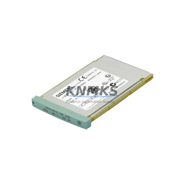
Prior to the maintenance window, the replacement 6ES7317-2AK14-0AB0 should be bench-tested with a copy of the production STEP 7 project. Load the program, hardware configuration, and all data blocks onto the new CPU using a PC Adapter USB or SIMATIC NET MPI/DP programming cable. Verify that the CPU reaches RUN mode without fault LEDs and that all OBs execute without errors in simulation. This offline validation step eliminates the most common causes of extended downtime: firmware incompatibility, corrupted MMC card data, and hardware configuration mismatches.
During the physical swap, the sequence is: (1) set the original CPU to STOP mode and confirm all outputs are de-energized or held by the field devices’ own safe-state logic; (2) remove the MMC memory card from the original CPU and insert it into the replacement unit as a backup reference; (3) disconnect the MPI and PROFIBUS DP connectors, noting the station address settings on each connector’s termination switch; (4) release the bus connector on the left side of the CPU and slide the module out of the rack; (5) install the replacement CPU, reconnect bus connector, MPI, and PROFIBUS DP cables; (6) power up and confirm the CPU reaches RUN mode; (7) perform a short functional test of critical I/O points before releasing the system to production.
If the original CPU failed before a program upload was possible, the STEP 7 project archive stored on the engineering workstation becomes the recovery source. All units supplied by KNMKS are tested for power-on functionality and communication port integrity before shipment, reducing the risk of receiving a non-functional replacement that would extend the downtime window further.
Retrofit Support FAQ
Q1: Is the 6ES7317-2AK14-0AB0 a direct drop-in replacement for the CPU315-2 DP or CPU316-2 DP?
Yes, mechanically and electrically. The backplane bus connector, rack mounting, and DIN rail format are identical across the S7-300 CPU family. However, the hardware configuration in STEP 7 must be updated to reflect the new CPU order number, and the program must be re-downloaded. Work memory capacity increases significantly, so existing program blocks will load without restructuring.
Q2: What firmware version is installed, and how do I verify compatibility with my STEP 7 project?
All units are supplied with the firmware version as specified at time of order. To verify compatibility, open your STEP 7 project in HW Config, select the CPU317-2 DP from the hardware catalog, and confirm the firmware version matches the unit’s front-panel label. If a firmware update is required, it can be performed via the MMC card using a SIMATIC Micro Memory Card programmer or directly through STEP 7 online functions.
Q3: Can I reuse the existing PROFIBUS DP network and field devices without reconfiguration?
Yes, provided the DP master station address on the replacement CPU is set to the same value as the original. PROFIBUS DP connectors carry the station address in their termination switch settings — confirm these before disconnecting. All slave devices (ET 200M, ET 200S, drives, valve terminals) will re-establish communication automatically once the master is online with the correct address and GSD-based configuration.
Q4: What does the support terms confirmed by quotation cover, and what is the shipping lead time?
The support terms confirmed by quotation cover manufacturing defects and functional failures under normal operating conditions. Each unit undergoes power-on testing and communication port verification before shipment. In-stock units typically ship within 1–3 business days. Express shipping options are available for urgent line-down situations. Contact admin@knmks.com or +86 18359268345 for stock confirmation and lead time on specific quantities.
© 2026 KNMKS. All rights reserved.
Original Source: https://knmks.com
Contact: admin@knmks.com | +86 18359268345
Product Identification
- Brand / Ecosystem
-
Siemens
Siemens - Model / Series
-
6ES7317-2AK14-0AB0
SIMATIC Series - Product Family
- PLCs & Controllers
- Availability Status
- Available on request after model and quantity confirmation
- Inquiry Type
- B2B RFQ, replacement inquiry and project spare-part request
- Pre-Quote Check
- Exact SKU, brand, series, quantity, nameplate photos and destination country are checked before quotation
System Path
Where this product fits in the KNMKS automation structure.
Specification & Inquiry Focus
- Control platform
- PLC, PAC and modular controllers
- Common needs
- CPU, rack, power and I/O expansion
- Project support
- Replacement, cabinet build and maintenance
Buyer Confirmation
Information KNMKS checks before replying.
- Exact model
- 6ES7317-2AK14-0AB0
- Brand / ecosystem
- Siemens
- Product family
- PLCs & Controllers
- Application note
- Replacement, maintenance, project build or spare-part list
- Useful photos
- Nameplate, installed unit, cabinet layout or connector side
- Delivery details
- Quantity, destination country and target schedule
Document Support
Files and notes can be confirmed during quotation.
- Product photos or nameplate confirmation when available
- Packing and delivery notes before quotation confirmation
- Support scope and delivery terms confirmed per inquiry
- Export document coordination for qualified B2B requests
Inquiry Support
- Model cross-checking before quotation
- CPU, power, rack and expansion module matching
- Support for replacement and project inquiry
What to Send Us
- Brand and exact model number: Siemens 6ES7317-2AK14-0AB0
- Quantity and required delivery time
- Application, replacement requirement or nameplate photo
- Destination country and shipping preference
RFQ Preparation
This is a product inquiry page built for RFQ communication.
Fast Model Check
Send this model to KNMKS for confirmation.
Include quantity, destination country and photos if this is a maintenance replacement. The inquiry will be saved with a reference number after submission.
Brand & Compatibility Note
KNMKS displays automation product information for well-known industrial brand ecosystems and compatible replacement references. Brand names are used for product identification and compatibility reference only; final availability and commercial terms are confirmed per quotation.
 Manufacturing
 Machine Tools
 Packaging
 Energy & Power
 HMI & Displays
 Servo Systems
 Variable Frequency Drives
 Sensors