
Overview
Siemens 6ES7231-7PB22-0XA0 Migration-Ready RTD Input for Legacy Control Systems
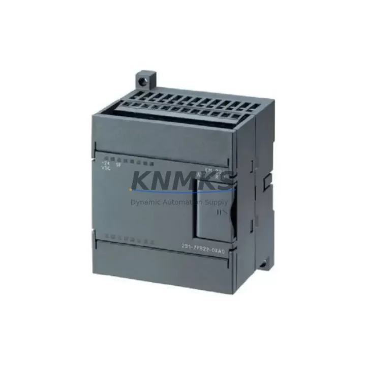
The Siemens 6ES7231-7PB22-0XA0 is a 2-channel RTD analog input module designed for the S7-200 SMART CPU platform. As legacy S7-200 systems reach end-of-life and facilities transition toward modernized control architectures, this module serves as a verified drop-in replacement and migration bridge — enabling engineers to extend operational life, restore discontinued spare parts, and maintain process continuity without full system overhaul.
Whether you are replacing a failed RTD input card in an aging control cabinet, retrofitting a legacy temperature monitoring loop, or preparing a phased migration from S7-200 to S7-200 SMART, the 6ES7231-7PB22-0XA0 delivers the signal accuracy, terminal compatibility, and firmware alignment required for reliable field deployment. Each unit is pre-shipment tested and backed by a support terms confirmed by quotation, ensuring confidence from procurement through commissioning.
Migration Compatibility Table
| Parameter | Details |
|---|---|
| Compatible Platform | Siemens S7-200 SMART CPU (ST20, ST30, ST40, ST60, CR40, CR60) |
| Legacy Replacement Target | S7-200 EM 231 RTD (6ES7231-7PB22-0XA0 series) |
| Input Channels | 2-channel RTD (Pt100, Pt1000, Ni100, Ni1000) |
| Terminal Wiring | 2-wire / 3-wire / 4-wire RTD configurations supported |
| Backplane Interface | S7-200 SMART expansion bus connector (right-side snap-on) |
| Power Supply | 5 VDC via CPU bus; 24 VDC sensor supply from external source |
| Module Address | Auto-assigned by CPU; verify AIW address offset in STEP 7-Micro/WIN SMART |
| Communication Protocol | Internal S7-200 SMART expansion bus (not Profibus/Profinet) |
| Installation Space | 35 mm DIN rail; module width 71.2 mm — confirm cabinet slot clearance |
| Firmware Compatibility | Compatible with STEP 7-Micro/WIN SMART V2.3 and above |
| Commissioning Note | Re-download program after module swap; verify AIW scaling in PLC logic |
| Support terms | support terms confirmed by quotation — pre-shipment tested, function verified |
Retrofit Planning for Existing Automation Systems
Integrating the 6ES7231-7PB22-0XA0 into an existing control cabinet requires a structured review of the surrounding system components. In most legacy S7-200 SMART installations, the CPU — such as the CPU ST40 or CPU CR60 — is mounted on a 35 mm DIN rail alongside expansion modules. Before swapping the RTD input card, engineers should audit the total expansion bus load: the S7-200 SMART CPU supports a maximum of 6 expansion modules, and adding or replacing a module shifts the AIW/AQW address mapping for all downstream analog modules.
Power budget verification is equally critical. The 6ES7231-7PB22-0XA0 draws 5 VDC from the CPU expansion bus. If the cabinet also houses a 6ES7288-3AE04-0AA0 EM AE04 (4-channel analog input) or a 6ES7288-3AQ02-0AA0 EM AQ02 (2-channel analog output), the cumulative 5 V bus current draw must remain within the CPU’s rated expansion power budget — typically 1,600 mA for larger CPUs. Exceeding this limit causes intermittent module faults and unreliable analog readings.
For installations that include temperature-to-process variable conversion loops feeding an HMI — such as a Siemens SMART 700 IE V3 or SMART 1000 IE V3 panel — the HMI screen tags referencing AIW addresses must be updated after module replacement. If the RTD module is inserted at a different slot position than the original, all downstream AIW offsets shift, and HMI numeric displays or trend screens will read incorrect values until the tag database is corrected and the HMI project is re-downloaded.
In retrofit scenarios involving communication protocol migration — for example, upgrading from a legacy RS-485 Modbus RTU network to Profinet — the 6ES7231-7PB22-0XA0 continues to operate on the internal expansion bus regardless of the CPU’s external communication configuration. However, if a 6ES7288-5CM08-0AA0 CM01 communication module is added to extend the CPU’s serial port capacity, its slot position must be accounted for in the expansion module count and address map.
For field wiring, the RTD sensor leads connect to the module’s removable terminal block. In 3-wire RTD configurations — the most common in industrial temperature loops — verify that the compensation wire resistance is balanced. Mismatched lead resistance introduces a fixed offset error that cannot be corrected in software without a known reference. If the original installation used 2-wire RTDs and the replacement specification calls for 3-wire, the field wiring must be updated before commissioning.
Downtime Control During System Migration
Minimizing production downtime during an RTD module replacement requires preparation before the maintenance window opens. The recommended approach is to export the existing STEP 7-Micro/WIN SMART project to a backup file and document all current AIW address assignments, scaling blocks (SCALE/UNSCALE instructions), and alarm setpoints that reference the RTD channels. This baseline ensures that if the replacement module triggers an address shift, the original logic can be restored or corrected within the maintenance window rather than during extended troubleshooting.
For systems where the RTD input feeds a closed-loop PID controller — for example, a furnace temperature control loop — the PID block should be placed in manual mode before the module is removed. This prevents the controller from driving the output actuator to its limit while the input signal is absent. After the 6ES7231-7PB22-0XA0 is installed and the CPU program is re-downloaded, verify the raw AIW value against a calibrated reference thermometer before returning the PID to automatic mode.
In multi-cabinet installations where the S7-200 SMART CPU communicates with a supervisory SCADA system via Ethernet, the CPU remains online during module hot-swap only if the system design supports it — the S7-200 SMART does not support true hot-swap of expansion modules. Plan for a controlled CPU stop, module replacement, program re-download, and CPU restart sequence. Coordinate with the SCADA operator to suppress alarms during the restart window to avoid false fault logging.
Pre-shipment testing of each 6ES7231-7PB22-0XA0 unit at our facility confirms channel accuracy, terminal integrity, and bus communication before dispatch. This eliminates the risk of receiving a defective module and discovering the fault only after the system has been taken offline — a scenario that significantly extends unplanned downtime. Combined with our support terms confirmed by quotation and in-stock availability, this module supports both emergency replacement and planned maintenance procurement strategies.
Retrofit Support FAQ
Q1: Is the 6ES7231-7PB22-0XA0 a direct replacement for the original S7-200 EM 231 RTD module?
The 6ES7231-7PB22-0XA0 is the S7-200 SMART platform equivalent of the legacy S7-200 EM 231 RTD. It is not physically interchangeable with the original S7-200 EM 231 due to the different expansion bus connector design. If you are migrating from S7-200 to S7-200 SMART, this module is the correct RTD input for the new platform. Confirm your CPU model before ordering.
Q2: Do I need to modify my PLC program after replacing the RTD module?
If the replacement module is installed in the same slot position as the original, the AIW address mapping remains unchanged and no program modification is required — only a program re-download to re-initialize the module. If the slot position changes, all AIW addresses for analog modules at that position and beyond will shift. Update all SCALE instructions, PID input references, and HMI tags accordingly before restarting the CPU.
Q3: What wiring configurations are supported, and how do I verify terminal compatibility?
The 6ES7231-7PB22-0XA0 supports 2-wire, 3-wire, and 4-wire RTD connections via its removable screw terminal block. Terminal pitch and block dimensions are compatible with standard 0.5–1.5 mm² field wiring. Before installation, photograph the existing terminal wiring and compare against the module’s terminal assignment diagram in the S7-200 SMART system manual. For 3-wire configurations, ensure all three leads are connected — leaving the compensation terminal open will result in a fixed measurement error.
Q4: What does the support terms confirmed by quotation cover, and is in-stock inventory available for urgent orders?
Each unit is covered by a support terms confirmed by quotation from the date of shipment, covering manufacturing defects and functional failures under normal operating conditions. All units are pre-shipment tested for channel accuracy and bus communication before dispatch. In-stock inventory is maintained for immediate shipment to support both emergency replacement and planned maintenance schedules. Contact our team for lead time confirmation and bulk pricing for multi-site procurement.
© 2026 KNMKS. All rights reserved.
Original Source: https://knmks.com
Contact: admin@knmks.com | +86 18359268345
Product Identification
- Brand / Ecosystem
-
Siemens
Siemens - Model / Series
-
6ES7231-7PB22-0XA0
SIMATIC Series - Product Family
- PLCs & Controllers
- Availability Status
- Available on request after model and quantity confirmation
- Inquiry Type
- B2B RFQ, replacement inquiry and project spare-part request
- Pre-Quote Check
- Exact SKU, brand, series, quantity, nameplate photos and destination country are checked before quotation
System Path
Where this product fits in the KNMKS automation structure.
Specification & Inquiry Focus
- Control platform
- PLC, PAC and modular controllers
- Common needs
- CPU, rack, power and I/O expansion
- Project support
- Replacement, cabinet build and maintenance
Buyer Confirmation
Information KNMKS checks before replying.
- Exact model
- 6ES7231-7PB22-0XA0
- Brand / ecosystem
- Siemens
- Product family
- PLCs & Controllers
- Application note
- Replacement, maintenance, project build or spare-part list
- Useful photos
- Nameplate, installed unit, cabinet layout or connector side
- Delivery details
- Quantity, destination country and target schedule
Document Support
Files and notes can be confirmed during quotation.
- Product photos or nameplate confirmation when available
- Packing and delivery notes before quotation confirmation
- Support scope and delivery terms confirmed per inquiry
- Export document coordination for qualified B2B requests
Inquiry Support
- Model cross-checking before quotation
- CPU, power, rack and expansion module matching
- Support for replacement and project inquiry
What to Send Us
- Brand and exact model number: Siemens 6ES7231-7PB22-0XA0
- Quantity and required delivery time
- Application, replacement requirement or nameplate photo
- Destination country and shipping preference
RFQ Preparation
This is a product inquiry page built for RFQ communication.
Fast Model Check
Send this model to KNMKS for confirmation.
Include quantity, destination country and photos if this is a maintenance replacement. The inquiry will be saved with a reference number after submission.
Brand & Compatibility Note
KNMKS displays automation product information for well-known industrial brand ecosystems and compatible replacement references. Brand names are used for product identification and compatibility reference only; final availability and commercial terms are confirmed per quotation.
 Manufacturing
 Machine Tools
 Packaging
 Energy & Power
 HMI & Displays
 Servo Systems
 Variable Frequency Drives
 Sensors