
Overview
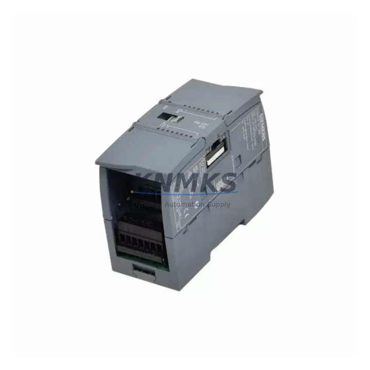
Siemens 6ES7231-5PD32-0XB0 Migration-Ready RTD Input Module for Legacy Control Systems
The Siemens 6ES7231-5PD32-0XB0 is a 4-channel RTD analog input module belonging to the SM 1231 signal module family, designed for integration into the SIMATIC S7-1200 controller platform. As industrial facilities accelerate the retirement of aging S7-200, S7-300, and early-generation S7-1200 hardware, this module has become a critical component in retrofit projects that demand precise temperature acquisition, minimal rewiring, and seamless program migration. Whether you are replacing a discontinued EM 231 RTD module from an S7-200 system or upgrading a degraded SM 331 from an S7-300 rack, the 6ES7231-5PD32-0XB0 provides a validated migration path with full compatibility across the TIA Portal engineering environment.
Each channel accepts standard RTD sensor types including Pt100, Pt200, Pt500, Pt1000, Ni100, and Ni1000, with configurable measurement ranges and wire compensation for 2-wire, 3-wire, and 4-wire sensor connections. The module mounts directly onto the S7-1200 CPU rail without additional adapters, occupying a single slot position and drawing supply power from the CPU backplane. Before installation, engineers should confirm available backplane current budget — the S7-1200 CPU 1214C, for example, provides up to 1600 mA on the 5 VDC bus, and a fully populated rack with multiple SM 1231 modules, a CM 1241 RS485 communications module, and an SM 1222 digital output module must be budgeted carefully to avoid brownout conditions during cold-start sequences.
Migration Compatibility Table
| Parameter | 6ES7231-5PD32-0XB0 (SM1231 RTD) | Legacy Reference (S7-300 SM331 / S7-200 EM231) |
|---|---|---|
| Channels | 4 × RTD (differential) | 2–8 channels (model-dependent) |
| Sensor Types | Pt100/200/500/1000, Ni100/1000, resistance | Pt100, Ni100 (limited range) |
| Wire Compensation | 2-wire, 3-wire, 4-wire | 2-wire or 3-wire only (SM331) |
| Backplane Interface | S7-1200 signal module bus | S7-300 backplane / S7-200 expansion bus |
| Engineering Tool | TIA Portal V13 SP1 and above | STEP 7 Classic / STEP 7 Micro/WIN |
| Terminal Wiring | 20-pin front connector (screw or push-in) | 40-pin sub-D (SM331) / 10-pin terminal (EM231) |
| Installation Width | 45 mm (1 slot) | 40–80 mm (varies by model) |
| Communication Protocol | PROFINET (via CPU), local bus | PROFIBUS DP (SM331) / proprietary (EM231) |
| Replacement Recommendation | Direct drop-in for S7-1200 expansions; adapter required for S7-300 rack | Program re-mapping required for address migration |
| Commissioning Focus | Sensor type config, wire mode, channel scaling in TIA Portal | Hardware catalog re-assignment, DB address update |
| Support terms | support terms confirmed by quotation — all units tested prior to shipment | |
Retrofit Planning for Existing Automation Systems
Successful integration of the 6ES7231-5PD32-0XB0 into a running production environment requires a structured pre-migration audit. Begin by documenting the existing I/O address map from the legacy PLC program — in STEP 7 Classic projects migrating to TIA Portal, the hardware configuration must be rebuilt from scratch, and all analog input process image addresses assigned to the old SM 331 or EM 231 must be remapped to the new module’s I/O range. This is typically handled through a symbol table migration and a global DB restructure.
Terminal wiring is one of the most time-sensitive tasks during a live-system cutover. The 6ES7231-5PD32-0XB0 uses a 20-pin removable front connector — if you are replacing a module in an existing S7-1200 rack, the connector can be pre-wired on the bench and swapped in under two minutes, significantly reducing exposure time. For systems migrating from S7-300 racks, new DIN rail sections and a replacement S7-1200 CPU — such as the CPU 1214C DC/DC/DC — will need to be mounted alongside the SM 1231 modules, and panel space must be confirmed before ordering. A typical 4-axis temperature monitoring cabinet may also require an SM 1222 8-output digital module for alarm relay control and a CM 1241 RS232 or RS485 module if legacy HMI panels communicate over serial protocols.
Power supply sizing is non-negotiable. If the existing cabinet uses a 24 VDC SITOP PSU100S or equivalent, verify that the load current budget accommodates the new CPU, all signal modules, and any retained field devices. An undersized supply is a leading cause of intermittent faults during the first weeks after retrofit. For larger expansions involving more than four SM 1231 RTD modules, consider distributing load across a secondary 24 VDC rail fed by a dedicated power supply module.
HMI screen migration is often underestimated. If the existing system uses a SIMATIC TP700 Comfort or KTP700 Basic panel connected via PROFINET, the tag database must be updated to reflect the new CPU IP address and revised DB variable paths. Panels connected via MPI or PROFIBUS to legacy S7-300 CPUs will require a communications protocol migration — typically to PROFINET — which may involve replacing the HMI panel itself or adding a protocol converter. Plan for at least one full HMI simulation test in TIA Portal before going live on the floor.
Downtime Control During System Migration
Minimizing unplanned downtime is the primary concern for any brownfield retrofit. The recommended approach is a parallel-run strategy: install the new S7-1200 CPU and 6ES7231-5PD32-0XB0 modules on a temporary DIN rail section within the same cabinet, wire all RTD sensors to both the old and new modules simultaneously using terminal block jumpers, and validate all channel readings against the legacy system before cutting over. This approach allows the engineering team to confirm sensor scaling, wire compensation mode, and process value accuracy without interrupting production.
Program logic protection is equally critical. Before any hardware change, export and archive the full STEP 7 or TIA Portal project, including all hardware configurations, symbol tables, data blocks, and HMI projects. Store backups on at least two independent media. During the cutover window, use the TIA Portal online diagnostic tools to monitor CPU scan cycle time, module status, and analog channel diagnostics in real time. If a channel fault is detected — commonly caused by an open-circuit RTD or incorrect wire mode selection — the module’s diagnostic buffer will log the fault code, allowing rapid identification without requiring a full system restart.
For facilities with strict SLA requirements, pre-staging the replacement module with the correct firmware version and a pre-loaded hardware configuration significantly reduces on-site commissioning time. All 6ES7231-5PD32-0XB0 units shipped from our inventory are tested for channel accuracy, backplane communication, and firmware integrity before dispatch. The support terms confirmed by quotation cover manufacturing defects and early-life failures, providing assurance during the critical post-retrofit stabilization period.
Retrofit Support FAQ
Q1: Can the 6ES7231-5PD32-0XB0 directly replace an SM 331 RTD module in an S7-300 system?
Not as a direct plug-in replacement — the S7-300 backplane bus and the S7-1200 signal module bus are physically and electrically incompatible. A full CPU migration to S7-1200 is required. However, the RTD sensor wiring, scaling parameters, and channel configuration logic are directly transferable, and TIA Portal’s migration wizard can assist with program structure conversion from STEP 7 Classic projects.
Q2: What firmware version is required for the 6ES7231-5PD32-0XB0, and how do I verify compatibility with my CPU?
The module requires TIA Portal V13 SP1 or later for full hardware support. CPU firmware V2.0 and above is recommended for stable analog module communication. Firmware version can be checked via the TIA Portal online device view or the CPU’s web server interface. All units we supply are shipped with current production firmware and include the hardware version printed on the module label for cross-reference.
Q3: How do I confirm correct terminal wiring when migrating from a 2-wire to a 3-wire RTD configuration?
The 6ES7231-5PD32-0XB0 front connector provides dedicated IC+, IC−, M+, and M− terminals per channel. For 3-wire Pt100 sensors, connect the single return wire to the M− terminal and bridge M+ to the sensor’s second return. Wire compensation mode must then be set to “3-wire” in the TIA Portal hardware configuration for that channel. Failure to match the physical wiring to the software configuration is the most common source of offset errors during initial commissioning.
Q4: What is your stock availability and support terms policy for this module?
We maintain ready stock of the 6ES7231-5PD32-0XB0 for immediate dispatch. Each unit undergoes pre-shipment functional testing covering channel accuracy, backplane interface, and firmware verification. A support terms confirmed by quotation is provided from the date of shipment, covering manufacturing defects and module-level failures under normal operating conditions. For urgent retrofit projects or bulk procurement, contact our sales team directly for lead time confirmation and volume pricing.
© 2026 KNMKS. All rights reserved.
Original Source: https://knmks.com
Contact: admin@knmks.com | +86 18359268345
Product Identification
- Brand / Ecosystem
-
Siemens
Siemens - Model / Series
-
6ES7231-5PD32-0XB0
SIMATIC Series - Product Family
- PLCs & Controllers
- Availability Status
- Available on request after model and quantity confirmation
- Inquiry Type
- B2B RFQ, replacement inquiry and project spare-part request
- Pre-Quote Check
- Exact SKU, brand, series, quantity, nameplate photos and destination country are checked before quotation
System Path
Where this product fits in the KNMKS automation structure.
Specification & Inquiry Focus
- Control platform
- PLC, PAC and modular controllers
- Common needs
- CPU, rack, power and I/O expansion
- Project support
- Replacement, cabinet build and maintenance
Buyer Confirmation
Information KNMKS checks before replying.
- Exact model
- 6ES7231-5PD32-0XB0
- Brand / ecosystem
- Siemens
- Product family
- PLCs & Controllers
- Application note
- Replacement, maintenance, project build or spare-part list
- Useful photos
- Nameplate, installed unit, cabinet layout or connector side
- Delivery details
- Quantity, destination country and target schedule
Document Support
Files and notes can be confirmed during quotation.
- Product photos or nameplate confirmation when available
- Packing and delivery notes before quotation confirmation
- Support scope and delivery terms confirmed per inquiry
- Export document coordination for qualified B2B requests
Inquiry Support
- Model cross-checking before quotation
- CPU, power, rack and expansion module matching
- Support for replacement and project inquiry
What to Send Us
- Brand and exact model number: Siemens 6ES7231-5PD32-0XB0
- Quantity and required delivery time
- Application, replacement requirement or nameplate photo
- Destination country and shipping preference
RFQ Preparation
This is a product inquiry page built for RFQ communication.
Fast Model Check
Send this model to KNMKS for confirmation.
Include quantity, destination country and photos if this is a maintenance replacement. The inquiry will be saved with a reference number after submission.
Brand & Compatibility Note
KNMKS displays automation product information for well-known industrial brand ecosystems and compatible replacement references. Brand names are used for product identification and compatibility reference only; final availability and commercial terms are confirmed per quotation.
 Manufacturing
 Machine Tools
 Packaging
 Energy & Power
 HMI & Displays
 Servo Systems
 Variable Frequency Drives
 Sensors