
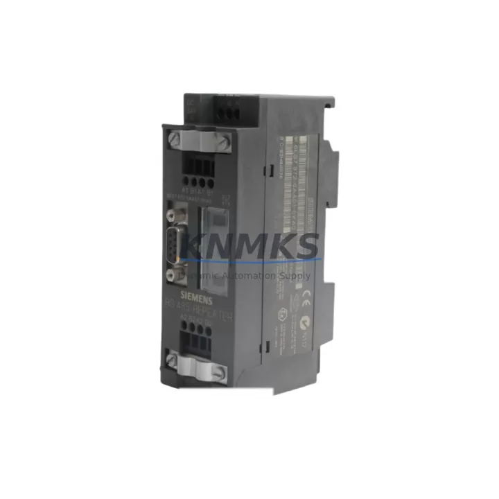
Overview
Siemens 6ES7183-0AA01-0XA0 Migration-Ready Interface for ET 200M: Legacy System Retrofit and Compatibility Upgrade
The Siemens 6ES7183-0AA01-0XA0 is the IM 153-1 interface module for the ET 200M distributed I/O station, designed to connect the ET 200M rack to a PROFIBUS DP master — typically a Siemens S7-300 or S7-400 CPU. As legacy automation lines age and OEM support for first-generation ET 200M configurations is phased out, this module has become a critical spare part and drop-in replacement for facilities managing long-lifecycle control systems. Whether you are restoring a failed station, expanding an existing PROFIBUS segment, or planning a phased migration away from discontinued hardware, the 6ES7183-0AA01-0XA0 provides a verified, field-proven path forward without requiring a full system redesign.
In retrofit and upgrade projects, the interface module sits at the heart of the ET 200M station architecture. It manages all communication between the PROFIBUS DP network and the signal modules installed in the local rack — including digital input/output modules such as the SM 321 and SM 322 series, analog modules from the SM 331 and SM 332 families, and specialty function modules. Before replacing the IM 153-1, engineers must confirm the PROFIBUS DP address configured on the existing module, as this address is set via rotary switches on the front face and must match the GSD file entry in the master configuration tool (typically STEP 7 or TIA Portal in legacy mode). Mismatched addresses will prevent the station from coming online and can trigger bus faults across the entire PROFIBUS segment.
Migration Compatibility Table
| Parameter | Details |
|---|---|
| Module Designation | IM 153-1 Interface Module for ET 200M |
| Order Number | 6ES7183-0AA01-0XA0 |
| Communication Interface | PROFIBUS DP (up to 12 Mbit/s) |
| Compatible Racks | ET 200M rack (UR1, UR2); up to 8 signal modules per station |
| Compatible Masters | Siemens S7-300 CPU with DP interface, S7-400 with CP 443-5, IM 308-C |
| Power Supply Requirement | 24 V DC via backplane bus; verify PS 307 or equivalent supply capacity before installation |
| Address Configuration | Rotary switch on module front; must match STEP 7 / TIA Portal hardware configuration |
| Firmware Compatibility | Compatible with STEP 7 V5.x and TIA Portal V13+ in legacy mode; verify GSD file version |
| Installation Space | Slot 1 of ET 200M rack (fixed position); confirm rack slot availability before ordering |
| Replacement Recommendation | Direct drop-in for failed or end-of-life IM 153-1 units; no program changes required if address and GSD match |
| Commissioning Notes | Set PROFIBUS address before power-up; perform bus diagnostics via STEP 7 online view after installation |
| Support terms | support terms confirmed by quotation — all units tested and verified before shipment |
Retrofit Planning for Existing Automation Systems
A successful ET 200M retrofit begins well before the replacement module arrives on site. The first step is a full audit of the existing station: document every signal module installed in the rack, record the I/O addresses assigned in the STEP 7 hardware configuration, and photograph the terminal wiring on each SM module. This documentation becomes the recovery baseline if anything goes wrong during the swap. Pay particular attention to the power supply module — the PS 307 5A or 10A unit feeding the rack must have sufficient headroom to support all installed signal modules plus the new interface module. Undersized power supplies are a common cause of intermittent faults after a module replacement.
On the PROFIBUS side, verify the network topology before disconnecting the existing IM 153-1. Check that the bus termination resistors are correctly placed at both physical ends of the PROFIBUS segment — removing an intermediate station without proper termination can destabilize the entire network. If the ET 200M station being retrofitted is the last node on the segment, ensure the replacement module is installed and powered before the bus is re-terminated. In multi-drop PROFIBUS configurations where the S7-300 CPU DP port is managing several ET 200M stations simultaneously, a single misconfigured station can cause all downstream stations to drop off the bus.
For facilities running mixed-generation hardware — for example, a control cabinet that combines an S7-300 CPU 315-2 DP with both ET 200M distributed I/O and older ET 200B compact stations — the retrofit scope must account for the different GSD files and diagnostic behaviors of each station type. The 6ES7183-0AA01-0XA0 is specific to the ET 200M modular architecture and is not interchangeable with the compact ET 200B or ET 200S interface modules. If the upgrade path involves migrating from ET 200M to ET 200SP, a new hardware configuration must be created in TIA Portal, new I/O addresses assigned, and the PLC program updated to reflect the new module mapping — a significantly larger scope than a like-for-like IM 153-1 replacement.
Communication protocol migration is another consideration for aging PROFIBUS-based systems. Some facilities are using the ET 200M retrofit as an opportunity to evaluate PROFINET migration using the IM 153-4 PN interface module, which fits the same ET 200M rack and supports the same signal module lineup. This approach preserves the existing field wiring and terminal assignments while upgrading the communication layer — a practical middle path between a full system replacement and a pure spare-part swap. The CP 343-1 communication processor is often added to the S7-300 rack in parallel to support PROFINET while the PROFIBUS segment remains operational during the transition period.
Downtime Control During System Migration
Minimizing unplanned downtime during an ET 200M interface module replacement requires a structured pre-outage preparation process. Before the maintenance window opens, the existing STEP 7 project should be uploaded from the CPU and saved to a secure backup location — never rely solely on the program resident in the PLC memory. If the CPU supports memory card backup, verify that the card contains the current program version and that the card is readable. For S7-300 systems without a memory card, use a PG/PC with STEP 7 installed to perform an online upload and save the project with a timestamped filename.
During the replacement, the signal modules and their terminal blocks remain in place — only the IM 153-1 in slot 1 is removed and replaced. This means field wiring is undisturbed, which significantly reduces recommissioning time. After installing the 6ES7183-0AA01-0XA0, set the PROFIBUS address using the rotary switches before applying power. Power up the rack, then use the STEP 7 online diagnostics or the TIA Portal device view to confirm that the station appears on the bus and that all signal modules are recognized. Check the diagnostic buffer of the CPU for any configuration mismatch errors — these typically indicate a GSD file version conflict or an address overlap with another station on the bus.
For critical production lines where even a brief interruption is costly, consider pre-staging the replacement module with the correct PROFIBUS address set and a bench test performed against a spare CPU or test rack before the maintenance window. This approach reduces the on-site replacement time to under 15 minutes in most cases and eliminates the risk of discovering a configuration issue during a live outage. All units supplied by KNMKS are pre-tested and shipped with a support terms confirmed by quotation, supporting your incoming inspection and commissioning confidence.
Retrofit Support FAQ
Q1: Is the 6ES7183-0AA01-0XA0 a direct replacement for my existing IM 153-1 without program changes?
Yes — provided the PROFIBUS address on the replacement module is set to match the original, and the GSD file in your STEP 7 or TIA Portal hardware configuration corresponds to the IM 153-1 variant. No PLC program changes are required for a like-for-like swap. Verify the hardware configuration version in STEP 7 matches the installed firmware of the new module before downloading.
Q2: How do I verify terminal wiring compatibility before replacing the interface module?
The signal modules (SM 321, SM 322, SM 331, SM 332, etc.) and their terminal blocks remain in the rack during the IM 153-1 replacement. Field wiring does not need to be disconnected. Document the I/O address assignments and module order in the rack before the swap, and confirm after power-up that all modules are recognized in the STEP 7 online view with no configuration faults.
Q3: What should I check if the ET 200M station does not come online after replacing the interface module?
First, confirm the PROFIBUS address set on the rotary switches matches the address in the hardware configuration. Second, check bus termination at both ends of the PROFIBUS segment. Third, verify the 24 V DC supply to the rack is within specification. Fourth, use the STEP 7 diagnostic buffer or the LED indicators on the IM 153-1 front panel to identify the fault code. Common issues include address conflicts, GSD file mismatches, and insufficient bus termination.
Q4: What is the support terms coverage and how are units tested before shipment?
All 6ES7183-0AA01-0XA0 units supplied by KNMKS carry a support terms confirmed by quotation from the date of shipment. Each unit undergoes functional testing prior to dispatch, including power-up verification and communication interface checks. In-stock units are available for same-day or next-business-day shipment. For bulk orders or blanket purchase agreements, contact our sales team to discuss lead times and inventory reservation options.
© 2026 KNMKS. All rights reserved.
Original Source: https://knmks.com
Contact: admin@knmks.com | +86 18359268345
Product Identification
- Brand / Ecosystem
-
Siemens
Siemens - Model / Series
-
6ES7183-0AA01-0XA0
SIMATIC Series - Product Family
- PLCs & Controllers
- Availability Status
- Available on request after model and quantity confirmation
- Inquiry Type
- B2B RFQ, replacement inquiry and project spare-part request
- Pre-Quote Check
- Exact SKU, brand, series, quantity, nameplate photos and destination country are checked before quotation
System Path
Where this product fits in the KNMKS automation structure.
Specification & Inquiry Focus
- Control platform
- PLC, PAC and modular controllers
- Common needs
- CPU, rack, power and I/O expansion
- Project support
- Replacement, cabinet build and maintenance
Buyer Confirmation
Information KNMKS checks before replying.
- Exact model
- 6ES7183-0AA01-0XA0
- Brand / ecosystem
- Siemens
- Product family
- PLCs & Controllers
- Application note
- Replacement, maintenance, project build or spare-part list
- Useful photos
- Nameplate, installed unit, cabinet layout or connector side
- Delivery details
- Quantity, destination country and target schedule
Document Support
Files and notes can be confirmed during quotation.
- Product photos or nameplate confirmation when available
- Packing and delivery notes before quotation confirmation
- Support scope and delivery terms confirmed per inquiry
- Export document coordination for qualified B2B requests
Inquiry Support
- Model cross-checking before quotation
- CPU, power, rack and expansion module matching
- Support for replacement and project inquiry
What to Send Us
- Brand and exact model number: Siemens 6ES7183-0AA01-0XA0
- Quantity and required delivery time
- Application, replacement requirement or nameplate photo
- Destination country and shipping preference
RFQ Preparation
This is a product inquiry page built for RFQ communication.
Fast Model Check
Send this model to KNMKS for confirmation.
Include quantity, destination country and photos if this is a maintenance replacement. The inquiry will be saved with a reference number after submission.
Brand & Compatibility Note
KNMKS displays automation product information for well-known industrial brand ecosystems and compatible replacement references. Brand names are used for product identification and compatibility reference only; final availability and commercial terms are confirmed per quotation.
 Manufacturing
 Machine Tools
 Packaging
 Energy & Power
 HMI & Displays
 Servo Systems
 Variable Frequency Drives
 Sensors