
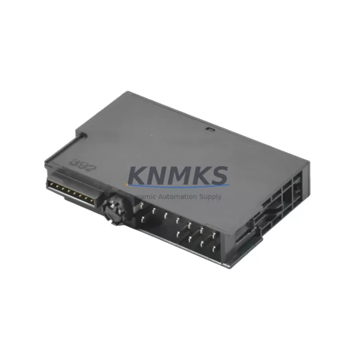
Overview
Siemens 6ES7134-4LB02-0AB0 Migration-Ready Analog Input: Legacy System Retrofit & Compatibility Upgrade
The Siemens 6ES7134-4LB02-0AB0 is a 4-channel analog input module designed for the ET 200S distributed I/O system, operating over PROFIBUS DP. As legacy automation lines face end-of-life pressures and spare part shortages, this module has become a critical component in retrofit projects across process manufacturing, automotive assembly, and infrastructure control systems. Whether you are replacing a discontinued predecessor, expanding an aging control cabinet, or migrating from an older S7-300 distributed I/O architecture, the 6ES7134-4LB02-0AB0 provides a verified, drop-in compatible solution with minimal re-engineering effort.
Before initiating a replacement, engineers must confirm several key parameters: the existing terminal wiring layout (2-wire vs. 4-wire transmitter connections), the power supply capacity of the ET 200S power module (typically the PM-E DC24V or PM-E F DC24V PP), the backplane slot assignment and module address configured in the PROFIBUS master, and the firmware version of the IM 151 interface module managing the ET 200S station. Mismatches in any of these areas can cause diagnostic faults or prevent the module from being recognized during startup. The 6ES7134-4LB02-0AB0 supports voltage and current input ranges configurable via STEP 7 or TIA Portal parameter assignment, so verifying that the existing program’s channel configuration blocks match the replacement module’s parameter set is essential before going live.
In control cabinet upgrade scenarios, installation space is often constrained. The ET 200S modular architecture allows the 6ES7134-4LB02-0AB0 to be inserted into any available slot on the terminal module rail without requiring additional mounting hardware, provided the correct terminal module (TM-E series) is already installed. If the original terminal module has been damaged or is missing, it must be sourced separately — the module itself does not include the terminal base. This is a common oversight during emergency replacements that can extend downtime unnecessarily.
For communication protocol migration projects — particularly those moving from older PROFIBUS DP Gen 1 configurations to newer ET 200SP or S7-1500 architectures — the 6ES7134-4LB02-0AB0 serves as a stable interim solution. It allows the field wiring and transmitter infrastructure to remain unchanged while the controller layer is upgraded. In such projects, the IM 151-1 or IM 151-3 PN interface module may also require a firmware update to maintain compatibility with the new CPU’s GSD file version. Coordinating this firmware update with the analog module replacement during a planned maintenance window is strongly recommended to avoid multiple separate outages.
HMI screen updates are another frequently overlooked element of analog input module replacements. If the original module’s diagnostic bits or channel status words were mapped to HMI tags in WinCC or a third-party SCADA system, the replacement module’s data structure must be verified to ensure tag addresses remain valid. In most ET 200S retrofit cases, the 6ES7134-4LB02-0AB0 maintains backward-compatible data structures, but this should be confirmed against the existing hardware configuration in STEP 7 HW Config before the cutover.
Signal isolation requirements should also be reviewed during the retrofit planning phase. In applications where ground loops or high common-mode voltages are present — common in older chemical processing or power generation facilities — a signal isolator or barrier may need to be inserted between the field transmitter and the analog input channel. This is independent of the module itself but is a critical commissioning consideration that affects measurement accuracy and module longevity.
Programming cable access is required during commissioning to verify the module’s parameter assignment and run a channel-by-channel input test. A standard PROFIBUS programming cable connected to the IM 151 interface module allows the technician to force individual channel reads and confirm that the analog values are being correctly transmitted to the CPU. This step should be completed before reconnecting field transmitters to avoid false process readings during startup.
Migration Compatibility Table
| Parameter | Details |
|---|---|
| SKU / Part Number | 6ES7134-4LB02-0AB0 |
| Series | Siemens ET 200S |
| Module Type | 4-Channel Analog Input |
| Communication Interface | PROFIBUS DP (via IM 151 interface module) |
| Input Signal Types | Voltage (±10V, 0–10V) / Current (0–20mA, 4–20mA) |
| Terminal Module Required | TM-E series (not included, must be ordered separately) |
| Compatible Interface Modules | IM 151-1, IM 151-3 PN |
| Power Supply Compatibility | PM-E DC24V, PM-E F DC24V PP |
| Installation | ET 200S rail-mount, any available slot |
| Firmware Compatibility | Verify IM 151 firmware version against GSD file |
| Programming Tool | STEP 7 v5.x / TIA Portal V13 and above |
| HMI Compatibility | WinCC, WinCC flexible, third-party SCADA (verify tag mapping) |
| Country of Origin | Germany |
| Support terms | 12 Months |
| Replacement Recommendation | Direct drop-in for same-series ET 200S analog input modules |
Retrofit Planning for Existing Automation Systems
A successful retrofit begins with a complete audit of the existing ET 200S station configuration. The IM 151 interface module defines the station’s PROFIBUS address and manages communication between the CPU and all installed I/O modules, including the 6ES7134-4LB02-0AB0. Before removing the old analog input module, the technician should export the current hardware configuration from STEP 7 HW Config and save a backup of the CPU program, including all data blocks and symbol tables.
The PM-E DC24V power module must be checked to confirm it can supply sufficient current for the replacement module alongside all other modules in the station. Adding a new analog input module to a station that is already near its power budget can cause intermittent faults or module dropouts under load. If the power budget is marginal, replacing the PM-E with a higher-capacity variant or splitting the station into two separate ET 200S segments should be considered.
For stations that include digital output modules such as the 6ES7132-4BD32-0AA0 DO module alongside the analog inputs, the slot order and module addressing must be preserved exactly as configured in the original hardware configuration file. Changing the slot sequence without updating the HW Config will cause a configuration mismatch fault at the PROFIBUS master and prevent the station from entering RUN mode.
In projects where the control system is being migrated from PROFIBUS DP to PROFINET — for example, upgrading from an S7-300 CPU with CP 342-5 to an S7-1500 with integrated PROFINET — the ET 200S station can be retained temporarily by using an IE/PB Link PN IO gateway. This allows the existing 6ES7134-4LB02-0AB0 analog input modules and their field wiring to remain in service while the controller migration is completed, significantly reducing the scope of the cutover and the associated downtime risk.
Where I/O expansion is required as part of the retrofit, additional ET 200S slots can be populated with supplementary analog input modules or digital I/O modules, provided the IM 151’s maximum module count and power budget are not exceeded. For applications requiring signal isolation between the field device and the PLC input, a DIN-rail mounted signal isolator can be inserted upstream of the terminal module without modifying the module itself or the existing program logic.
Downtime Control During System Migration
Minimizing downtime during an analog input module replacement requires careful pre-staging and a clearly defined cutover sequence. The replacement 6ES7134-4LB02-0AB0 should be parameter-assigned and bench-tested offline before being brought to the plant floor. Using a PROFIBUS programming cable and a laptop running STEP 7 or TIA Portal, the technician can verify that the module responds correctly to simulated input signals and that all four channels report values within the expected range before installation.
During the cutover, the CPU should be placed in STOP mode and the ET 200S station de-energized before removing the old module. The terminal module wiring should be photographed and documented before disconnection. If the terminal module itself is being replaced, all field wiring must be carefully re-terminated and verified with a continuity check before re-energizing the station.
After installation, the CPU should be restarted in a controlled sequence: first confirm that the PROFIBUS master recognizes the ET 200S station and that no configuration mismatch faults are present, then verify that all analog input channels are reporting plausible values before releasing the process to automatic control. If the system includes a WinCC or SCADA HMI, the operator should confirm that all analog trend displays and alarm setpoints are functioning correctly before the maintenance window is closed.
For critical processes where even brief interruptions are unacceptable, a hot-standby approach using a redundant ET 200S station can be considered. However, in most retrofit scenarios, a well-planned 2–4 hour maintenance window is sufficient to complete the module replacement, parameter verification, and functional test for a single ET 200S station.
Retrofit Support FAQ
Q: Is the 6ES7134-4LB02-0AB0 a direct replacement for older ET 200S analog input modules?
A: Yes, in most cases it is a direct drop-in replacement for earlier 4-channel analog input modules in the ET 200S series, provided the terminal module (TM-E) is already installed and the hardware configuration in STEP 7 is updated to reflect the replacement module’s order number. Always verify the parameter assignment matches the original module’s configuration before restarting the station.
Q: What commissioning steps are required after installation?
A: After physical installation, connect a PROFIBUS programming cable to the IM 151 interface module and use STEP 7 or TIA Portal to download the updated hardware configuration to the CPU. Perform a channel-by-channel input test by applying known reference signals to each analog input and confirming the reported values match the expected engineering units. Check the CPU diagnostic buffer for any module-related faults before returning the system to automatic operation.
Q: How do I verify wiring compatibility with my existing field transmitters?
A: The 6ES7134-4LB02-0AB0 supports both 2-wire and 4-wire transmitter connections. Check the existing terminal module wiring diagram to confirm the transmitter type and connection method. For 2-wire (loop-powered) transmitters, ensure the module’s channel is configured for current input mode (4–20mA) in the parameter assignment. For voltage-output transmitters, select the appropriate voltage range. Wiring changes are made at the terminal module level and do not require modification of the module itself.
Q: What does the support terms confirmed by quotation cover, and is pre-shipment testing performed?
A: All units are functionally tested prior to shipment to verify correct operation across all input channels. The support terms confirmed by quotation cover manufacturing defects and functional failures under normal operating conditions. Units are shipped with appropriate ESD protection packaging. For urgent retrofit requirements, expedited shipping options are available. Contact admin@knmks.com or call +86 18359268345 to confirm current stock availability and lead times.
© 2026 KNMKS. All rights reserved.
Original Source: https://knmks.com
Contact: admin@knmks.com | +86 18359268345
Product Identification
- Brand / Ecosystem
-
Siemens
Siemens - Model / Series
-
6ES7134-4LB02-0AB0
SIMATIC Series - Product Family
- PLCs & Controllers
- Availability Status
- Available on request after model and quantity confirmation
- Inquiry Type
- B2B RFQ, replacement inquiry and project spare-part request
- Pre-Quote Check
- Exact SKU, brand, series, quantity, nameplate photos and destination country are checked before quotation
System Path
Where this product fits in the KNMKS automation structure.
Specification & Inquiry Focus
- Control platform
- PLC, PAC and modular controllers
- Common needs
- CPU, rack, power and I/O expansion
- Project support
- Replacement, cabinet build and maintenance
Buyer Confirmation
Information KNMKS checks before replying.
- Exact model
- 6ES7134-4LB02-0AB0
- Brand / ecosystem
- Siemens
- Product family
- PLCs & Controllers
- Application note
- Replacement, maintenance, project build or spare-part list
- Useful photos
- Nameplate, installed unit, cabinet layout or connector side
- Delivery details
- Quantity, destination country and target schedule
Document Support
Files and notes can be confirmed during quotation.
- Product photos or nameplate confirmation when available
- Packing and delivery notes before quotation confirmation
- Support scope and delivery terms confirmed per inquiry
- Export document coordination for qualified B2B requests
Inquiry Support
- Model cross-checking before quotation
- CPU, power, rack and expansion module matching
- Support for replacement and project inquiry
What to Send Us
- Brand and exact model number: Siemens 6ES7134-4LB02-0AB0
- Quantity and required delivery time
- Application, replacement requirement or nameplate photo
- Destination country and shipping preference
RFQ Preparation
This is a product inquiry page built for RFQ communication.
Fast Model Check
Send this model to KNMKS for confirmation.
Include quantity, destination country and photos if this is a maintenance replacement. The inquiry will be saved with a reference number after submission.
Brand & Compatibility Note
KNMKS displays automation product information for well-known industrial brand ecosystems and compatible replacement references. Brand names are used for product identification and compatibility reference only; final availability and commercial terms are confirmed per quotation.
 Manufacturing
 Machine Tools
 Packaging
 Energy & Power
 HMI & Displays
 Servo Systems
 Variable Frequency Drives
 Sensors