
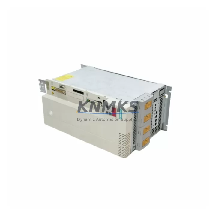
Overview
Siemens 6ES7023-8TP60-Z Migration-Ready Interface Module for Legacy S7-300 Systems
The Siemens 6ES7023-8TP60-Z is a migration-ready Interface Module (IM) engineered for SIMATIC S7-300 distributed I/O architectures. As legacy S7-300 control systems approach end-of-life and spare parts become increasingly scarce, this IM module provides a reliable, drop-in compatible solution for engineers managing aging production lines, control cabinet upgrades, and multi-rack expansion retrofits. Whether you are replacing a failed unit in an emergency shutdown scenario or executing a planned system modernization, the 6ES7023-8TP60-Z delivers the backplane compatibility, communication link integrity, and installation footprint required to maintain operational continuity without reprogramming the entire control structure.
In distributed S7-300 installations, the IM module serves as the physical and logical bridge between the central rack and expansion racks. The 6ES7023-8TP60-Z supports the standard S7-300 backplane bus interface, allowing it to integrate directly into existing rack assemblies without mechanical modification. Engineers replacing a failed IM in a live production environment must verify the rack slot assignment, confirm the module address configured in STEP 7 or TIA Portal, and ensure that the firmware revision on the replacement unit is compatible with the CPU currently managing the rack — typically a CPU 315-2 DP, CPU 317-2 PN/DP, or CPU 319-3 PN/DP. Mismatched firmware versions between the IM send and IM receive pair can cause rack initialization failures that are not immediately obvious during cold start diagnostics.
Terminal wiring on the 6ES7023-8TP60-Z follows the standard S7-300 connector pinout. Before removal of the legacy unit, engineers should document all terminal assignments and verify that the power supply module — commonly a PS 307 5A or PS 307 10A — is delivering stable 24 VDC within the tolerance range required by the IM module. Voltage fluctuations during rack power-up are a frequent cause of IM initialization errors in aging control cabinets where capacitors in the power supply have degraded over years of continuous operation.
For installations where the S7-300 rack communicates over PROFIBUS DP, the IM module replacement must be followed by a bus address verification step. The PROFIBUS DP address assigned to the expansion rack must match the configuration stored in the CPU project. In multi-drop PROFIBUS networks, an address conflict introduced during IM replacement can disrupt communication across all downstream nodes, including remote I/O stations, variable frequency drives, and field instruments connected to the same segment. Engineers should use a PROFIBUS diagnostic tool or the integrated diagnostic buffer in the CPU to confirm bus integrity before returning the system to automatic mode.
When the retrofit scope extends beyond a single IM replacement to a broader control cabinet upgrade — for example, migrating from S7-300 to S7-1500 — the 6ES7023-8TP60-Z can serve as a stabilization component during the transition phase. By maintaining the existing S7-300 expansion rack in service while the new S7-1500 CPU and ET 200MP I/O modules are commissioned in parallel, engineers can execute a phased cutover that minimizes production downtime. During this transition, the SM 321 digital input modules, SM 322 digital output modules, and SM 331 analog input modules in the expansion rack continue to operate under the legacy CPU, preserving the original ladder logic and function block structure until the new program is validated and ready for switchover.
HMI screen updates are a frequently underestimated element of IM replacement projects. If the control system includes a SIMATIC TP or MP panel communicating with the CPU via MPI or PROFIBUS, the HMI project must be reviewed to confirm that rack slot references and I/O addresses remain consistent after the IM swap. Address shifts caused by incorrect slot configuration in STEP 7 can produce silent data errors in HMI displays, where analog values appear plausible but are sourced from incorrect memory addresses. A full I/O force test following IM replacement is strongly recommended before resuming automated production sequences.
Installation space confirmation is essential in densely populated control cabinets. The 6ES7023-8TP60-Z occupies a standard S7-300 module slot width. Engineers should verify that adjacent modules — including CP 343-1 communication processors, FM 350 counter modules, or SM 374 placeholder modules — are not obstructing the connector engagement path. In cabinets where DIN rail mounting has been modified or where cable management has reduced clearance, a physical dry-fit of the replacement module before final installation prevents connector damage during insertion.
All units supplied are pre-shipment tested under simulated rack conditions, confirming backplane bus communication, power rail integrity, and IM send/receive handshake before dispatch. Stock is maintained across multiple warehouse locations to support emergency replacement timelines. A support terms confirmed by quotation cover all supplied modules against manufacturing defects and communication failures under normal operating conditions.
Migration Compatibility Table
| Parameter | Details |
|---|---|
| SKU / Part Number | 6ES7023-8TP60-Z (Z-G91-K80) |
| Series | SIMATIC S7-300 |
| Module Type | Interface Module (IM) — Send/Receive |
| Backplane Interface | S7-300 standard backplane bus |
| Communication Compatibility | PROFIBUS DP, MPI |
| Compatible CPUs | CPU 315-2 DP, CPU 317-2 PN/DP, CPU 319-3 PN/DP |
| Installation Requirement | Standard S7-300 DIN rail rack, single slot width |
| Power Supply Requirement | 24 VDC via rack backplane (PS 307 5A / 10A compatible) |
| Replacement Recommendation | Direct drop-in for failed or end-of-life 6ES7023-8TP60-Z units |
| Firmware Compatibility | Verify IM send/receive firmware revision match before installation |
| Commissioning Note | Confirm PROFIBUS DP address, rack slot, and module address in STEP 7 / TIA Portal |
| Pre-Shipment Testing | Yes — backplane bus, power rail, IM handshake verified |
| Support terms | 12 Months |
| Origin | Germany |
| Global Dispatch | Available — multi-location stock |
Retrofit Planning for Existing Automation Systems
A successful S7-300 retrofit begins with a complete audit of the existing rack configuration. In a typical multi-rack installation, the central rack houses the CPU, power supply, and communication processor, while expansion racks connected via the 6ES7023-8TP60-Z IM pair carry the bulk of the I/O load. Before ordering replacement modules, engineers should document the exact slot positions of all SM 321 digital input modules, SM 322 digital output modules, SM 331 analog input modules, and any FM 350 counter or positioning modules installed in the expansion rack. This documentation becomes the reference baseline for post-replacement I/O verification.
The power budget of the expansion rack must be recalculated when adding new modules during a retrofit. The PS 307 power supply feeding the rack has a defined current capacity, and adding higher-density I/O modules or replacing older SM modules with newer variants can push the rack beyond its rated load. A current consumption audit using the module data sheets prevents unexpected power-related faults after commissioning.
Communication module placement is equally important. If the expansion rack includes a CP 343-1 Ethernet communication processor for supervisory SCADA connectivity, its slot position and IP address configuration must be preserved exactly during the IM replacement. SCADA systems polling the CP 343-1 via Modbus TCP or S7 communication will lose data if the module is inadvertently moved to a different slot, as the slot number forms part of the logical addressing structure in some STEP 7 configurations.
For systems where signal isolation is required between field instruments and the S7-300 I/O, signal isolators installed on the terminal rail adjacent to the rack must be verified for loop continuity after the IM swap. A broken signal path at the isolator terminal — caused by vibration during module removal — can produce false analog readings that are difficult to distinguish from a genuine process deviation without a dedicated loop calibration check.
Programming cable access is required if the CPU needs to be taken offline for a project download following the IM replacement. A PC adapter USB or MPI/PROFIBUS programming cable connected to the CPU MPI port allows engineers to perform a partial download of the hardware configuration without interrupting the entire program. This approach is preferred in installations where a full CPU restart would trigger safety interlocks or process shutdowns.
Downtime Control During System Migration
Minimizing downtime during an IM module replacement in a live S7-300 system requires a structured pre-maintenance sequence. Before removing the failed IM, the CPU should be placed in STOP mode and the expansion rack powered down in a controlled sequence — power supply off before backplane disconnection — to prevent transient voltages from damaging adjacent modules. The original program and hardware configuration should be backed up to the programming device before any physical intervention, ensuring that a restore path exists if the replacement module triggers unexpected configuration errors during initialization.
Once the replacement 6ES7023-8TP60-Z is installed and the rack is powered up, the CPU diagnostic buffer should be checked immediately for any IM-related fault entries. Common post-replacement faults include rack address mismatch, IM firmware incompatibility, and backplane bus termination errors. Each of these can be resolved without a full system restart if identified early in the commissioning sequence.
To protect the original program logic during the migration, engineers should avoid downloading a modified hardware configuration unless the slot assignments have actually changed. An unnecessary hardware configuration download can reset module parameters and force a cold restart of the CPU, which in turn triggers all output modules to their safe-state positions — a condition that may activate downstream safety relays or process interlocks if not anticipated in the shutdown procedure.
Field control continuity can be maintained during brief IM replacement windows by placing the process in manual control mode at the DCS or SCADA level, allowing operators to hold critical setpoints manually while the PLC rack is offline. This approach is particularly effective in batch process environments where individual unit operations can be paused without affecting the broader production sequence. A target replacement window of under 30 minutes is achievable with a pre-staged replacement module, documented wiring references, and a pre-loaded hardware configuration file ready for download.
Retrofit Support FAQ
Q: Is the 6ES7023-8TP60-Z a direct replacement for the original Siemens unit?
A: Yes. The 6ES7023-8TP60-Z is a direct form-fit-function replacement for the original Siemens SIMATIC S7-300 Interface Module of the same part number. No mechanical modification, wiring change, or program edit is required for a like-for-like swap, provided the firmware revision of the replacement unit is compatible with the paired IM and the CPU hardware configuration.
Q: What commissioning steps are required after installation?
A: After physical installation, power up the rack and check the CPU diagnostic buffer for IM-related fault entries. Verify the PROFIBUS DP bus address if applicable, confirm the rack slot assignment in STEP 7 or TIA Portal, and perform a full I/O force test to validate that all digital and analog signals are correctly mapped. If the CPU reports a hardware configuration mismatch, a partial hardware configuration download may be required.
Q: How is wiring compatibility confirmed before installation?
A: The 6ES7023-8TP60-Z uses the standard S7-300 backplane connector. No field wiring connects directly to the IM module — all I/O wiring terminates at the signal modules (SM) in the rack. Wiring compatibility verification focuses on the power supply connections to the rack and the PROFIBUS DP cable termination at the bus connector on the IM module, if applicable.
Q: What does the support terms confirmed by quotation cover, and is pre-shipment testing performed?
A: All units undergo pre-shipment testing covering backplane bus communication, power rail integrity, and IM send/receive handshake verification. The support terms confirmed by quotation cover manufacturing defects and communication failures under normal operating conditions. Units showing physical damage caused by incorrect installation, overvoltage, or environmental contamination are excluded from support terms coverage.
© 2026 KNMKS. All rights reserved.
Original Source: https://knmks.com
Contact: admin@knmks.com | +86 18359268345
Product Identification
- Brand / Ecosystem
-
Siemens
Siemens - Model / Series
-
6ES7023-8TP60-Z Z-G91-K80
SIMATIC Series - Product Family
- PLCs & Controllers
- Availability Status
- Available on request after model and quantity confirmation
- Inquiry Type
- B2B RFQ, replacement inquiry and project spare-part request
- Pre-Quote Check
- Exact SKU, brand, series, quantity, nameplate photos and destination country are checked before quotation
System Path
Where this product fits in the KNMKS automation structure.
Specification & Inquiry Focus
- Control platform
- PLC, PAC and modular controllers
- Common needs
- CPU, rack, power and I/O expansion
- Project support
- Replacement, cabinet build and maintenance
Buyer Confirmation
Information KNMKS checks before replying.
- Exact model
- 6ES7023-8TP60-Z Z-G91-K80
- Brand / ecosystem
- Siemens
- Product family
- PLCs & Controllers
- Application note
- Replacement, maintenance, project build or spare-part list
- Useful photos
- Nameplate, installed unit, cabinet layout or connector side
- Delivery details
- Quantity, destination country and target schedule
Document Support
Files and notes can be confirmed during quotation.
- Product photos or nameplate confirmation when available
- Packing and delivery notes before quotation confirmation
- Support scope and delivery terms confirmed per inquiry
- Export document coordination for qualified B2B requests
Inquiry Support
- Model cross-checking before quotation
- CPU, power, rack and expansion module matching
- Support for replacement and project inquiry
What to Send Us
- Brand and exact model number: Siemens 6ES7023-8TP60-Z Z-G91-K80
- Quantity and required delivery time
- Application, replacement requirement or nameplate photo
- Destination country and shipping preference
RFQ Preparation
This is a product inquiry page built for RFQ communication.
Fast Model Check
Send this model to KNMKS for confirmation.
Include quantity, destination country and photos if this is a maintenance replacement. The inquiry will be saved with a reference number after submission.
Brand & Compatibility Note
KNMKS displays automation product information for well-known industrial brand ecosystems and compatible replacement references. Brand names are used for product identification and compatibility reference only; final availability and commercial terms are confirmed per quotation.
 Manufacturing
 Machine Tools
 Packaging
 Energy & Power
 HMI & Displays
 Servo Systems
 Variable Frequency Drives
 Sensors