
Overview
Siemens 6DS1213-8AA Migration-Ready Coupler for Legacy DCS: Retrofit and Compatibility Upgrade
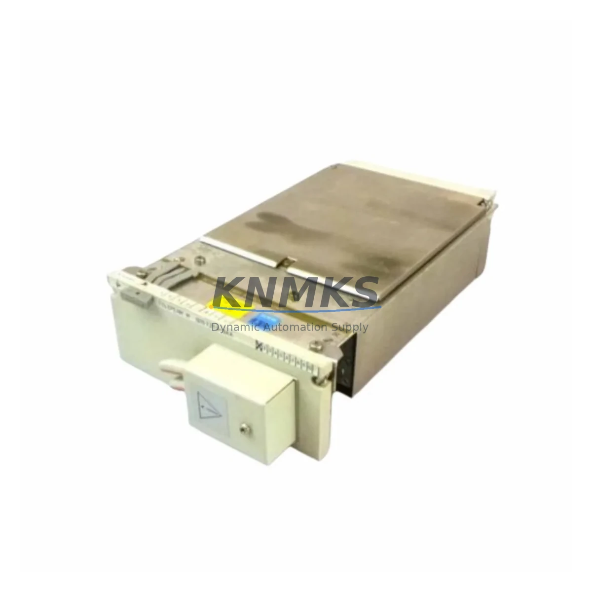
The Siemens 6DS1213-8AA is a DCS coupler module designed for the TELEPERM M distributed control system — one of Siemens’ most widely deployed process automation platforms across petrochemical, power generation, and heavy manufacturing facilities. As TELEPERM M has reached end-of-life status, many plant operators face the critical challenge of sourcing verified replacement modules to sustain production continuity without committing to a full DCS migration. The 6DS1213-8AA addresses this need directly: it is a drop-in coupler replacement that maintains backplane compatibility, preserves existing terminal wiring, and supports the communication architecture of legacy TELEPERM M control cabinets.
For engineers managing aging control infrastructure, the 6DS1213-8AA represents a low-risk, high-value retrofit option. Rather than replacing an entire control rack or reengineering the I/O architecture, maintenance teams can swap the coupler module, verify firmware compatibility, and restore system operation — often within a single planned maintenance window. This approach significantly reduces downtime exposure and defers the capital expenditure of a full platform migration.
Migration Compatibility Table
| Parameter | Details |
|---|---|
| SKU / Part Number | 6DS1213-8AA |
| Series | TELEPERM M (TM) |
| Module Type | DCS Coupler Module |
| Backplane Interface | Compatible with TELEPERM M standard rack backplane |
| Terminal Wiring | Retains original terminal block layout; no rewiring required in most retrofit scenarios |
| Communication Compatibility | Supports TELEPERM M internal bus protocol; verify firmware revision before installation |
| Installation Form Factor | Standard TELEPERM M module slot; confirm rack slot clearance and adjacent module spacing |
| Replacement Recommendation | Direct replacement for failed or end-of-life 6DS1213-8AA units in existing TELEPERM M racks |
| Commissioning Notes | Confirm module address assignment, HMI tag mapping, and communication link status post-installation |
| Firmware Verification | Match firmware version to existing rack configuration before energizing |
| Power Supply Requirement | Verify rack power supply capacity (typically 6DS1606 or equivalent) supports additional module load |
| Support terms | support terms confirmed by quotation — functional testing completed prior to shipment |
Retrofit Planning for Existing Automation Systems
Successful integration of the 6DS1213-8AA into a legacy TELEPERM M system requires a structured pre-installation assessment. Before the module arrives on-site, the engineering team should audit the existing rack configuration, document the current module address map, and confirm that the rack power supply — commonly a 6DS1606 series power supply module — has sufficient headroom to support the replacement coupler without triggering undervoltage conditions on adjacent I/O modules.
Terminal wiring compatibility is a primary concern in any coupler retrofit. The 6DS1213-8AA uses the standard TELEPERM M terminal block interface, which means field wiring from sensors, transmitters, and actuators typically does not require modification. However, engineers should verify signal types, shielding continuity, and grounding integrity before re-energizing the loop. In installations where the control cabinet also houses a 6DS1702 or 6DS1703 series analog input module, cross-referencing the signal range configuration ensures that the coupler’s data path remains consistent with the upstream controller expectations.
Communication link integrity is equally critical. In TELEPERM M architectures, the coupler module serves as the interface between field I/O and the central controller bus. After module replacement, the communication link between the 6DS1213-8AA and the TELEPERM M central controller — often a 6DS1100 or 6DS1101 series unit — must be re-established and verified through the system’s diagnostic interface. Any mismatch in module addressing or bus configuration will prevent the controller from recognizing the new module, resulting in fault states that can affect the entire control loop.
For plants that also operate SIMATIC S5 or early SIMATIC S7 controllers in adjacent control zones, the retrofit of a TELEPERM M coupler module may coincide with a broader communication protocol migration. In these environments, a CP 5431 or equivalent PROFIBUS communication processor may already be present in the control cabinet, and its configuration should be reviewed to ensure that the coupler replacement does not disrupt inter-system data exchange. Similarly, if the facility uses a 6XV1 series PROFIBUS cable infrastructure, cable continuity and termination resistance should be confirmed after any rack-level intervention.
HMI screen updates are often overlooked during coupler replacements. If the plant’s operator interface — whether a legacy WinCC installation or a panel-based HMI — references specific module tags tied to the 6DS1213-8AA’s I/O channels, those tag assignments must be verified post-installation to ensure that process values are displayed correctly and that alarm thresholds remain active. Skipping this step is a common source of post-retrofit incidents during the first hours of resumed production.
Downtime Control During System Migration
Minimizing unplanned downtime is the primary operational objective when replacing a coupler module in a live TELEPERM M system. The recommended approach is to perform the replacement during a scheduled maintenance window, with a pre-staged 6DS1213-8AA module that has been bench-tested and firmware-verified before it reaches the plant floor. This eliminates the risk of discovering a configuration mismatch after the original module has already been removed from the rack.
Before de-energizing the affected rack slot, the control program logic should be placed in a safe hold state. In TELEPERM M systems, this typically involves switching the affected control loops to manual mode at the operator station, confirming that all downstream actuators — valves, drives, and interlocks — are in a known safe position, and documenting the current process values for reference during recommissioning. Preserving the original program logic is non-negotiable: no changes should be made to the controller’s function block configuration during a coupler swap, as any unintended modification can introduce control errors that are difficult to trace after the system is back online.
Once the replacement 6DS1213-8AA is installed and the rack is re-energized, the commissioning sequence should follow a structured checklist: confirm module recognition in the system diagnostic display, verify communication link status, check I/O channel assignments, restore control loops to automatic mode one at a time, and monitor process values for stability over a minimum observation period before declaring the retrofit complete. This disciplined approach consistently reduces total downtime to within the planned maintenance window and avoids the extended troubleshooting cycles that result from rushed or undocumented replacements.
Retrofit Support FAQ
Q: Is the 6DS1213-8AA a direct drop-in replacement for the original module in my TELEPERM M rack?
A: In the majority of TELEPERM M installations, yes. The 6DS1213-8AA maintains the standard backplane connector and terminal block interface of the TELEPERM M module family. Before installation, confirm the rack slot dimensions, module address configuration, and firmware revision to ensure full compatibility with your specific system version.
Q: What commissioning steps are required after installing the replacement module?
A: After physical installation, verify module address assignment via the system diagnostic interface, confirm communication link status between the coupler and the central controller, check I/O channel mapping against the original configuration, and restore control loops to automatic mode sequentially. HMI tag assignments should also be verified to ensure process values are displayed correctly at the operator station.
Q: How do I confirm that my rack power supply can support the replacement module?
A: Review the power budget of your existing rack power supply — typically a 6DS1606 or equivalent unit — by summing the current draw of all installed modules and comparing it against the supply’s rated output. The 6DS1213-8AA’s power consumption specification should be confirmed against the available headroom before installation to avoid undervoltage conditions.
Q: What support terms and pre-shipment testing does this module include?
A: Every 6DS1213-8AA unit is functionally tested prior to shipment and covered by a support terms confirmed by quotation. Stock availability is maintained to support urgent replacement requirements. For lead time confirmation or technical pre-sales support, contact admin@knmks.com or call +86 18359268345.
© 2026 KNMKS. All rights reserved. Original Source: https://knmks.com | Contact: admin@knmks.com | +86 18359268345
Product Identification
- Brand / Ecosystem
-
Siemens
Siemens - Model / Series
-
6DS1213-8AA
Legacy Series - Product Family
- PLCs & Controllers
- Availability Status
- Available on request after model and quantity confirmation
- Inquiry Type
- B2B RFQ, replacement inquiry and project spare-part request
- Pre-Quote Check
- Exact SKU, brand, series, quantity, nameplate photos and destination country are checked before quotation
System Path
Where this product fits in the KNMKS automation structure.
Specification & Inquiry Focus
- Control platform
- PLC, PAC and modular controllers
- Common needs
- CPU, rack, power and I/O expansion
- Project support
- Replacement, cabinet build and maintenance
Buyer Confirmation
Information KNMKS checks before replying.
- Exact model
- 6DS1213-8AA
- Brand / ecosystem
- Siemens
- Product family
- PLCs & Controllers
- Application note
- Replacement, maintenance, project build or spare-part list
- Useful photos
- Nameplate, installed unit, cabinet layout or connector side
- Delivery details
- Quantity, destination country and target schedule
Document Support
Files and notes can be confirmed during quotation.
- Product photos or nameplate confirmation when available
- Packing and delivery notes before quotation confirmation
- Support scope and delivery terms confirmed per inquiry
- Export document coordination for qualified B2B requests
Inquiry Support
- Model cross-checking before quotation
- CPU, power, rack and expansion module matching
- Support for replacement and project inquiry
What to Send Us
- Brand and exact model number: Siemens 6DS1213-8AA
- Quantity and required delivery time
- Application, replacement requirement or nameplate photo
- Destination country and shipping preference
RFQ Preparation
This is a product inquiry page built for RFQ communication.
Fast Model Check
Send this model to KNMKS for confirmation.
Include quantity, destination country and photos if this is a maintenance replacement. The inquiry will be saved with a reference number after submission.
Brand & Compatibility Note
KNMKS displays automation product information for well-known industrial brand ecosystems and compatible replacement references. Brand names are used for product identification and compatibility reference only; final availability and commercial terms are confirmed per quotation.
 Manufacturing
 Machine Tools
 Packaging
 Energy & Power
 HMI & Displays
 Servo Systems
 Variable Frequency Drives
 Sensors