
Overview
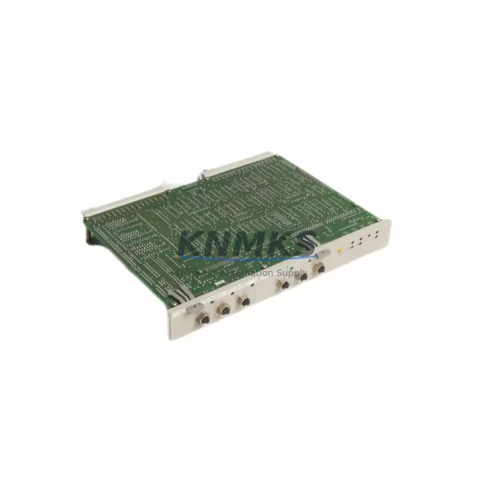
Siemens 6DS1124-8AA Migration-Ready Monitor Coupler for Legacy DCS: Retrofit and Compatibility Upgrade
The Siemens 6DS1124-8AA is a monitor coupler module designed for the TELEPERM M distributed control system platform — one of Siemens’ most widely deployed process automation architectures in the chemical, petrochemical, power generation, and water treatment industries. As TELEPERM M hardware reaches end-of-life and spare parts become increasingly scarce, the 6DS1124-8AA remains a critical component for plants that must maintain operational continuity while planning a phased migration to modern DCS platforms such as SIMATIC PCS 7 or SPPA-T3000.
This module functions as the communication bridge between the TELEPERM M central controller and the process monitoring subsystem, enabling real-time data exchange, alarm forwarding, and operator interface connectivity. Its role in the control architecture makes it indispensable during any retrofit project where the existing HMI infrastructure, including legacy OS stations and process displays, must remain operational while backend controllers are upgraded incrementally.
Migration Compatibility Table
| Parameter | Specification / Retrofit Note |
|---|---|
| Module Designation | 6DS1124-8AA — Monitor Coupler for TELEPERM M |
| Mounting / Installation | TELEPERM M subrack (S5-compatible backplane slot); confirm physical slot dimensions before installation |
| Backplane Interface | TELEPERM M internal bus; verify bus termination resistors on adjacent slots |
| Power Supply Requirement | 24 V DC via backplane; confirm power budget of existing 6DS1703-8AA or equivalent PSU module before adding load |
| Terminal Wiring | Existing field wiring can be retained; verify terminal block pin assignments against original loop drawings |
| Communication Protocol | TELEPERM M proprietary monitor bus; not directly compatible with PROFIBUS or Industrial Ethernet without gateway |
| Firmware Compatibility | Compatible with TELEPERM M firmware revisions up to the last supported release; confirm OS software version before replacement |
| HMI Screen Compatibility | Existing process displays and alarm pages remain functional; no HMI reconfiguration required for like-for-like swap |
| Replacement Recommendation | Direct drop-in replacement for failed or end-of-life 6DS1124-8AA units; no program changes required |
| Commissioning Focus | Verify module address switches match original configuration; confirm monitor link status LEDs after power-up |
| Support terms | support terms confirmed by quotation — covers manufacturing defects and functional failure under normal operating conditions |
Retrofit Planning for Existing Automation Systems
Successful integration of the 6DS1124-8AA into an ongoing retrofit project requires careful coordination across multiple system layers. Before removing the failed or end-of-life module, engineers should document the existing module address configuration using the DIP switch settings visible on the front face of the unit. These address settings determine how the monitor coupler is identified on the TELEPERM M internal bus, and an incorrect address after replacement will prevent the OS station from re-establishing communication with the controller.
Power capacity planning is equally important. The TELEPERM M subrack relies on dedicated power supply modules — typically the 6DS1703-8AA series — to distribute 24 V DC across all installed modules. Before inserting a replacement 6DS1124-8AA, verify that the existing power supply has sufficient headroom to support the module’s current draw, particularly in racks where additional I/O modules such as the 6DS1400-8AA analog input module or 6DS1500-8AA digital input module have been added as part of an I/O expansion project.
Terminal wiring from the field instrumentation loop should be carefully labeled and photographed before disconnection. In many legacy installations, the original loop drawings may not reflect field modifications made over decades of operation. Retaining the original wiring harness and reconnecting it to the replacement module using the same terminal assignments eliminates the risk of signal inversion or cross-wiring errors that can cause process upsets during commissioning.
For plants that are simultaneously upgrading their operator interface infrastructure, the 6DS1124-8AA supports continued operation of existing TELEPERM M OS stations during the transition period. If the migration plan includes moving to a SIMATIC PCS 7 environment, a protocol gateway or coupler — such as those in the SIMATIC NET CP series — will be required to bridge the proprietary TELEPERM M monitor bus to PROFIBUS DP or Industrial Ethernet. Planning this gateway integration early in the project timeline prevents last-minute delays caused by incompatible communication stacks.
In control cabinets where space is constrained, confirm that the replacement 6DS1124-8AA module fits within the existing subrack without requiring mechanical modification. The module occupies a standard TELEPERM M slot width; however, in older installations where non-standard spacers or cable management brackets have been added, physical clearance should be verified before ordering. Signal isolators or barriers installed between the field terminals and the module input circuits should also be inspected and tested as part of the retrofit scope, since degraded isolation can cause intermittent faults that are difficult to diagnose after the new module is installed.
Downtime Control During System Migration
Minimizing unplanned downtime during a TELEPERM M module replacement is achievable with disciplined pre-work. The most effective approach is to perform a full backup of the controller program and configuration data using the TELEPERM M programming tool before any hardware is disturbed. This backup preserves all function block parameters, loop tuning values, alarm limits, and interlock logic, ensuring that the control program can be restored to its exact pre-maintenance state if an unexpected issue arises during the swap.
Where process conditions permit, the replacement should be scheduled during a planned maintenance window rather than as an emergency repair. This allows time to verify the replacement module’s firmware version against the system’s compatibility matrix, confirm that the module address switches are set correctly before installation, and perform a controlled power-down of the affected subrack rather than a hot-swap, which is not supported on all TELEPERM M backplane variants.
After the replacement 6DS1124-8AA is installed and the subrack is powered up, the commissioning sequence should begin with a visual inspection of the module’s status LEDs. A steady green RUN indicator confirms that the module has initialized correctly and established communication with the TELEPERM M central controller. The OS station should then be checked to confirm that all process variables previously displayed through the monitor coupler are being received correctly, with no spurious alarms or communication fault messages. If the plant uses a separate historian or data acquisition system connected through the monitor bus, verify that data logging has resumed before releasing the loop back to automatic control.
For plants managing multiple simultaneous retrofit activities — such as replacing both the 6DS1124-8AA monitor coupler and upgrading adjacent communication modules — a staged approach that completes and verifies each module replacement before proceeding to the next significantly reduces the risk of compounding faults that are difficult to isolate under time pressure.
Retrofit Support FAQ
Q: Is the 6DS1124-8AA a direct drop-in replacement for the original module without program changes?
A: Yes. The 6DS1124-8AA is a like-for-like replacement for the original module of the same part number. No changes to the TELEPERM M controller program, function block configuration, or HMI display pages are required, provided the module address switches are set to match the original configuration before installation.
Q: What pre-shipment testing is performed on the 6DS1124-8AA?
A: Each unit undergoes functional power-on testing and communication interface verification before dispatch. Units are inspected for physical condition, connector integrity, and correct LED initialization. A test report is available upon request for critical spare applications.
Q: How do I confirm wiring compatibility before installation?
A: Compare the terminal block pin assignments on the replacement module against the original loop drawings for your installation. In most cases, the field wiring can be transferred directly from the old module to the new unit without modification. If loop drawings are unavailable, the wiring can be traced from the field instrument back to the terminal block before disconnection.
Q: What does the support terms confirmed by quotation cover?
A: The support terms confirmed by quotation cover manufacturing defects and functional failure under normal operating conditions from the date of shipment. It does not cover damage resulting from incorrect installation, overvoltage, reverse polarity, or physical impact. Support requests are processed through our sales team at admin@knmks.com.
© 2026 KNMKS. All rights reserved.
Original Source: https://knmks.com
Contact: admin@knmks.com | +86 18359268345
Product Identification
- Brand / Ecosystem
-
Siemens
Siemens - Model / Series
-
6DS1124-8AA
Legacy Series - Product Family
- Other Components
- Availability Status
- Available on request after model and quantity confirmation
- Inquiry Type
- B2B RFQ, replacement inquiry and project spare-part request
- Pre-Quote Check
- Exact SKU, brand, series, quantity, nameplate photos and destination country are checked before quotation
System Path
Where this product fits in the KNMKS automation structure.
Specification & Inquiry Focus
- Component range
- Breakers, terminals and cabinet accessories
- Common needs
- Model, photo and installation requirement
- Project support
- Maintenance and mixed spare-part inquiry
Buyer Confirmation
Information KNMKS checks before replying.
- Exact model
- 6DS1124-8AA
- Brand / ecosystem
- Siemens
- Product family
- Other Components
- Application note
- Replacement, maintenance, project build or spare-part list
- Useful photos
- Nameplate, installed unit, cabinet layout or connector side
- Delivery details
- Quantity, destination country and target schedule
Document Support
Files and notes can be confirmed during quotation.
- Product photos or nameplate confirmation when available
- Packing and delivery notes before quotation confirmation
- Support scope and delivery terms confirmed per inquiry
- Export document coordination for qualified B2B requests
Inquiry Support
- Mixed automation spare parts inquiry
- Cabinet component and accessory support
- Model identification from photos or labels
What to Send Us
- Brand and exact model number: Siemens 6DS1124-8AA
- Quantity and required delivery time
- Application, replacement requirement or nameplate photo
- Destination country and shipping preference
RFQ Preparation
This is a product inquiry page built for RFQ communication.
Fast Model Check
Send this model to KNMKS for confirmation.
Include quantity, destination country and photos if this is a maintenance replacement. The inquiry will be saved with a reference number after submission.
Brand & Compatibility Note
KNMKS displays automation product information for well-known industrial brand ecosystems and compatible replacement references. Brand names are used for product identification and compatibility reference only; final availability and commercial terms are confirmed per quotation.
 Manufacturing
 Machine Tools
 Packaging
 Energy & Power
 PLCs & Controllers
 HMI & Displays
 Servo Systems
 Variable Frequency Drives