
Overview
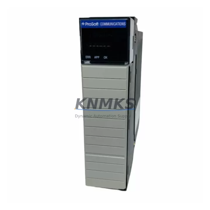
ProSoft MVI56E-MCM Migration-Ready Serial Module for Legacy Control Systems
The ProSoft MVI56E-MCM (Multi-Channel Multi-Protocol Serial Communication Module) is a proven migration-ready solution for engineers modernizing legacy ControlLogix-based automation systems. Designed for direct installation into the Allen-Bradley 1756 backplane, the MVI56E-MCM supports RS-232, RS-422, and RS-485 physical layers across two independent serial ports, enabling simultaneous multi-protocol communication without additional hardware conversion layers.
For facilities operating aging serial-dependent control architectures — including systems originally built around the MVI56-MCM, MVI56-MNET, or earlier ProSoft serial bridge modules — the MVI56E-MCM provides a validated upgrade path that preserves existing field wiring, terminal block layouts, and ladder logic structures. Its enhanced firmware supports Modbus RTU Master/Slave, Modbus ASCII, DF1 Full-Duplex, DF1 Half-Duplex, and generic ASCII protocols, making it compatible with a wide range of legacy PLCs, drives, meters, and third-party field devices that remain in service across older production lines.
When planning a retrofit from the original MVI56-MCM to the MVI56E-MCM, engineers must verify several critical parameters before cutover. Power draw from the 1756 backplane should be confirmed against the chassis power supply capacity — the MVI56E-MCM draws 800 mA at 5 VDC from the backplane, and installations sharing slots with high-draw I/O modules such as the 1756-IB32 or analog modules like the 1756-IF16 must account for total chassis current budget. Terminal block wiring on the RJ45-to-DB9 breakout cables must be re-verified against the new module’s pinout documentation, as signal ground references and handshaking lines differ between module generations.
Backplane slot addressing in the RSLogix 5000 or Studio 5000 project file must be updated to reflect the MVI56E-MCM’s new slot assignment. The module’s internal configuration is managed through ProSoft Configuration Builder (PCB), which replaces the older ProSoft Configuration Manager used with legacy MVI56 variants. Engineers should export and archive the original MCM configuration file before migration, then re-import and validate all port settings, baud rates, parity, stop bits, and protocol-specific parameters within PCB prior to going live.
HMI screens built on PanelView Plus terminals or third-party SCADA systems that reference serial-sourced data tags must be reviewed for tag path changes introduced by the new module’s MSG instruction structure. In systems where the MVI56E-MCM interfaces with variable frequency drives — such as legacy PowerFlex 40 or PowerFlex 700 units communicating via Modbus RTU — the drive node addresses, polling rates, and exception response handling must be re-validated after module swap.
Communication link continuity is especially critical in systems where the serial module bridges data between the ControlLogix controller and remote RTUs, flow computers, or energy meters. The MVI56E-MCM’s enhanced event-driven data transfer and configurable command queuing reduce polling latency compared to the original MVI56-MCM, but this behavioral change must be accounted for in ladder logic timing rungs and MSG instruction timeout settings. Where the control system also includes a 1756-EN2T EtherNet/IP communication module for supervisory connectivity, engineers should confirm that the updated module data table structure does not conflict with existing produced/consumed tag configurations.
Physical installation space within the 1756 chassis must be confirmed. The MVI56E-MCM occupies a single slot in any standard 1756 chassis — including the 1756-A4, 1756-A7, 1756-A10, and 1756-A17 — and is compatible with both ControlLogix and GuardLogix platforms. Firmware version compatibility between the module and the Logix controller firmware should be verified using ProSoft’s published compatibility matrix before field installation.
Pre-shipment functional testing is performed on every MVI56E-MCM unit, covering backplane communication integrity, serial port loopback verification, and protocol handshake validation. Each unit ships with a support terms confirmed by quotation covering manufacturing defects and functional failures under normal operating conditions, with documented traceability for spare parts lifecycle management.
Migration Compatibility Table
| Parameter | Legacy MVI56-MCM | MVI56E-MCM (Replacement) | Migration Notes |
|---|---|---|---|
| Backplane Interface | 1756 ControlLogix | 1756 ControlLogix / GuardLogix | Direct slot-for-slot replacement; verify chassis current budget |
| Serial Ports | 2 × RS-232/422/485 | 2 × RS-232/422/485 | Re-verify pinout on breakout cables; signal ground references differ |
| Supported Protocols | Modbus RTU/ASCII, DF1, ASCII | Modbus RTU/ASCII, DF1 FD/HD, ASCII, enhanced event-driven | Re-validate MSG timeout settings; polling behavior updated |
| Configuration Tool | ProSoft Configuration Manager | ProSoft Configuration Builder (PCB) | Export legacy config before migration; re-import in PCB |
| Backplane Current Draw | ~800 mA @ 5 VDC | 800 mA @ 5 VDC | Confirm chassis power supply headroom with co-installed modules |
| Chassis Compatibility | 1756-A4/A7/A10/A17 | 1756-A4/A7/A10/A17 | Single-slot; confirm physical slot availability |
| Firmware Compatibility | RSLogix 5000 v16+ | Studio 5000 / RSLogix 5000 v16+ | Verify controller firmware version against ProSoft compatibility matrix |
| HMI Tag Paths | Legacy MSG-based tag structure | Updated MSG instruction structure | Review PanelView Plus / SCADA tag paths for data table changes |
| Support terms | Varies (legacy/used stock) | 12 Months | New unit; documented traceability for spare parts lifecycle |
Retrofit Planning for Existing Automation Systems
A successful MVI56E-MCM retrofit begins with a full audit of the existing control cabinet. Engineers should document every module installed in the 1756 chassis — including the chassis power supply model (e.g., 1756-PA72 or 1756-PB72), all I/O modules, and any co-installed communication modules — before calculating available backplane current headroom. In multi-chassis systems connected via the 1756-RM redundancy module or 1756-DHRIO remote I/O bridge, the MVI56E-MCM’s slot assignment must be planned to avoid address conflicts with existing remote I/O node mappings.
For systems where the legacy serial module was bridging Modbus RTU data from third-party energy meters, flow computers, or weighing controllers, the MVI56E-MCM’s configurable command list must be rebuilt in ProSoft Configuration Builder to match the original polling sequence. Engineers should capture all original baud rate, parity, stop bit, and node address settings from the legacy configuration file before decommissioning the old module.
In control cabinets where DIN rail space is constrained, the MVI56E-MCM’s single-slot 1756 form factor eliminates the need for external serial converters or signal isolators that were sometimes added to compensate for legacy module limitations. Where RS-485 multi-drop networks connect multiple field devices — such as variable speed drives, motor protection relays, or remote I/O adapters — the termination resistor placement and cable shielding grounding must be re-verified after module replacement to prevent communication errors on long cable runs.
Systems that include a 1756-L71 or 1756-L73 ControlLogix controller with existing produced/consumed tag relationships should have their controller project files backed up and version-controlled before any slot reassignment. The MVI56E-MCM’s add-on instruction (AOI) and user-defined data type (UDT) structures should be imported into the Studio 5000 project and validated offline before the physical module swap is performed on the live system.
Downtime Control During System Migration
Minimizing unplanned downtime during a serial module migration requires a structured pre-cutover checklist. Before removing the legacy MVI56-MCM, engineers should perform a full online backup of the ControlLogix project, export the ProSoft configuration file, and document all active serial communication status indicators and error counters. This baseline data allows rapid fault isolation if communication issues arise after the MVI56E-MCM is installed.
Where production schedules permit only short maintenance windows, the MVI56E-MCM can be pre-configured and bench-tested against a spare 1756 chassis before the live cutover. ProSoft Configuration Builder supports offline configuration, allowing engineers to build, validate, and simulate the full port configuration — including protocol command lists, data table mappings, and error handling routines — without requiring the module to be installed in the production chassis.
During the physical swap, the original field wiring to the serial breakout cables should be photographed and labeled before disconnection. After installing the MVI56E-MCM and downloading the validated configuration, engineers should bring up one serial port at a time, monitoring the module’s onboard LED status indicators and the RSLinx or Studio 5000 diagnostic screens for backplane communication confirmation before enabling the second port and resuming full production polling cycles.
In systems where continuous process control cannot be interrupted, a parallel installation strategy — using a temporary spare slot in the chassis to run the MVI56E-MCM alongside the legacy module during a validation period — can reduce cutover risk. Once the new module’s data tables are confirmed to match the legacy module’s output, the ladder logic can be switched to reference the new module’s tags during a planned brief stop, keeping total downtime to under 15 minutes in most installations.
Retrofit Support FAQ
Q1: Is the MVI56E-MCM a direct drop-in replacement for the legacy MVI56-MCM?
The MVI56E-MCM is a functional replacement for the MVI56-MCM and installs in the same 1756 backplane slot. However, it requires reconfiguration using ProSoft Configuration Builder (PCB) rather than the legacy ProSoft Configuration Manager. Ladder logic MSG instructions and data table references must be reviewed and updated in the Studio 5000 project before going live. Physical wiring to the serial breakout cables should be re-verified against the MVI56E-MCM pinout documentation.
Q2: What serial protocols does the MVI56E-MCM support, and are they compatible with my existing field devices?
The MVI56E-MCM supports Modbus RTU Master/Slave, Modbus ASCII, DF1 Full-Duplex, DF1 Half-Duplex, and generic ASCII protocols across both serial ports independently. This covers the majority of legacy field devices — including drives, meters, RTUs, and third-party controllers — that communicate via RS-232, RS-422, or RS-485. Protocol-specific parameters (baud rate, parity, stop bits, node address) must be matched to the existing field device configuration during commissioning.
Q3: What pre-shipment testing is performed, and what does the support terms confirmed by quotation cover?
Every MVI56E-MCM unit undergoes pre-shipment functional testing covering backplane communication integrity, serial port loopback verification, and protocol handshake validation. The support terms confirmed by quotation cover manufacturing defects and functional failures under normal operating conditions from the date of shipment. Each unit includes documented traceability to support spare parts lifecycle management and procurement audit requirements.
Q4: How quickly can the MVI56E-MCM be sourced for emergency replacement of a failed legacy serial module?
Stock availability is maintained to support urgent replacement requirements for facilities experiencing unplanned serial communication failures. Lead time and current inventory status can be confirmed directly with the sales team. For critical spare parts programs, multi-unit stocking agreements are available to ensure on-site availability and reduce exposure to extended downtime from single-point serial module failures.
© 2026 KNMKS. All rights reserved.
Original Source: https://knmks.com
Contact: admin@knmks.com | +86 18359268345
Product Identification
- Brand / Ecosystem
-
ProSoft Technology
Assorted Brands - Model / Series
-
MVI56E-MCM
Legacy Series - Product Family
- PLCs & Controllers
- Availability Status
- Available on request after model and quantity confirmation
- Inquiry Type
- B2B RFQ, replacement inquiry and project spare-part request
- Pre-Quote Check
- Exact SKU, brand, series, quantity, nameplate photos and destination country are checked before quotation
System Path
Where this product fits in the KNMKS automation structure.
Specification & Inquiry Focus
- Control platform
- PLC, PAC and modular controllers
- Common needs
- CPU, rack, power and I/O expansion
- Project support
- Replacement, cabinet build and maintenance
Buyer Confirmation
Information KNMKS checks before replying.
- Exact model
- MVI56E-MCM
- Brand / ecosystem
- ProSoft Technology
- Product family
- PLCs & Controllers
- Application note
- Replacement, maintenance, project build or spare-part list
- Useful photos
- Nameplate, installed unit, cabinet layout or connector side
- Delivery details
- Quantity, destination country and target schedule
Document Support
Files and notes can be confirmed during quotation.
- Product photos or nameplate confirmation when available
- Packing and delivery notes before quotation confirmation
- Support scope and delivery terms confirmed per inquiry
- Export document coordination for qualified B2B requests
Inquiry Support
- Model cross-checking before quotation
- CPU, power, rack and expansion module matching
- Support for replacement and project inquiry
What to Send Us
- Brand and exact model number: ProSoft Technology MVI56E-MCM
- Quantity and required delivery time
- Application, replacement requirement or nameplate photo
- Destination country and shipping preference
RFQ Preparation
This is a product inquiry page built for RFQ communication.
Fast Model Check
Send this model to KNMKS for confirmation.
Include quantity, destination country and photos if this is a maintenance replacement. The inquiry will be saved with a reference number after submission.
Brand & Compatibility Note
KNMKS displays automation product information for well-known industrial brand ecosystems and compatible replacement references. Brand names are used for product identification and compatibility reference only; final availability and commercial terms are confirmed per quotation.
 Manufacturing
 Machine Tools
 Packaging
 Energy & Power
 HMI & Displays
 Servo Systems
 Variable Frequency Drives
 Sensors