
Overview
KNMKS 330104-09-20-10-01-00 Migration-Ready Proximity Transducer: Legacy System Retrofit & Upgrade Guide
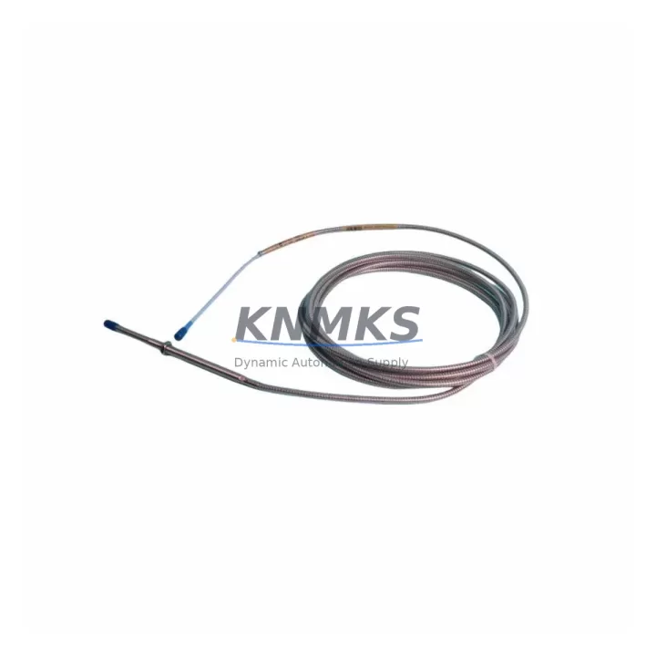
The Bently Nevada 330104-09-20-10-01-00 is an 8mm proximity transducer engineered for the 3300 XL continuous machinery monitoring platform. As legacy Bently Nevada 3300 Series installations approach end-of-life and OEM support windows close, plant engineers and reliability teams are increasingly tasked with executing controlled migrations — replacing discontinued transducer assemblies, recalibrating monitor modules, and validating signal integrity across the entire measurement chain without triggering unplanned shutdowns.
This unit is a direct migration-ready replacement for obsolete 330104-series transducers previously installed in turbine, compressor, pump, and motor monitoring cabinets. It maintains the standard 5-metre integral cable configuration, -24 VDC bias voltage output, and 200 mV/mil (7.87 V/mm) sensitivity that the 3300 XL Monitor expects — eliminating the need for signal conditioning adapters or firmware reconfiguration in most retrofit scenarios.
Migration Compatibility Table
| Parameter | 330104-09-20-10-01-00 (This Unit) | Legacy / Discontinued Reference | Retrofit Notes |
|---|---|---|---|
| Probe Diameter | 8 mm | 8 mm (330104 series) | Direct mechanical fit; no adapter required |
| Cable Length | 5 m integral | 5 m integral | Verify conduit routing; extension cables may be added |
| Sensitivity | 200 mV/mil (7.87 V/mm) | 200 mV/mil | No monitor rescaling required |
| Bias Voltage | -24 VDC nominal | -24 VDC | Confirm driver output; check 3300 XL Driver module |
| Linear Range | 0.25 mm – 2.26 mm | 0.25 mm – 2.26 mm | Re-gap per OEM spec after installation |
| Connector Type | Standard BNC / integral | BNC / integral | Verify terminal block wiring at monitor input card |
| Communication / Protocol | Analog (passive transducer) | Analog | No protocol migration required; compatible with 3300 XL rack |
| Mounting Thread | M10 × 1 | M10 × 1 | Confirm thread condition in existing boss; re-tap if worn |
| Installation Space | Standard probe boss | Standard probe boss | No housing modification required |
| API 670 Compliance | Yes | Yes | Suitable for turbine and compressor protection systems |
| Firmware / Calibration | Factory calibrated | Factory calibrated | Perform gap voltage verification on-site after installation |
| Support terms | support terms confirmed by quotation — covers manufacturing defects; includes pre-shipment functional test report | ||
Retrofit Planning for Existing Automation Systems
A successful retrofit of the 330104-09-20-10-01-00 into an operating plant begins well before the maintenance window opens. The first step is a full audit of the existing 3300 XL rack — confirming which monitor slots are occupied, verifying that the 3300 XL Proximitor/Seismic Monitor cards are still within their calibration cycle, and documenting the current gap voltage readings for each installed transducer. This baseline data becomes the acceptance criterion for the replacement units.
On the wiring side, engineers must trace each transducer cable from the probe boss through the conduit to the terminal block on the monitor input card. The 3300 XL I/O Module terminal assignments — typically labelled COM, SIG, and PWR — must be verified against the replacement transducer’s pinout before any disconnection occurs. Where cable runs exceed the standard 5-metre integral length, a compatible 3300 XL Extension Cable (such as the 330130 series) should be pre-staged to avoid improvised field splices that can introduce noise into the vibration signal.
Power supply capacity is a critical checkpoint. The 3300 XL Power Supply Module feeding the rack must be confirmed to have sufficient headroom to support all active channels simultaneously, particularly in cabinets where additional I/O cards or communication modules have been added over the years. A rack drawing review — cross-referenced against the current power budget — prevents nuisance trips during commissioning.
For plants running integrated condition monitoring, the System 1 Evolution software configuration must be reviewed to ensure that the channel tag, engineering unit scaling, and alarm setpoints associated with the replaced transducer are preserved. If the HMI faceplate displays gap voltage as a diagnostic parameter, the new transducer’s factory gap voltage certificate should be used to update the reference value in the historian. This prevents false gap-loss alarms during the first hours of operation after restart.
In cabinets where the 3300 XL Keyphasor Module is installed alongside radial vibration channels, the phase reference signal must be re-verified after transducer replacement to confirm that the once-per-revolution trigger is still correctly aligned. Any drift in the Keyphasor gap voltage — caused by probe boss wear or shaft surface condition changes — should be corrected before the machine is returned to service, as it affects all vector-based vibration measurements across the rack.
Finally, where plants are executing a broader migration from the legacy 3300 Series to a newer monitoring architecture, the 330104-09-20-10-01-00 serves as a bridge component — maintaining measurement continuity on the existing rack while the migration plan for the monitor cards, communication gateways, and historian integration is finalised. This phased approach avoids the risk of a full-system cutover during a single maintenance window.
Downtime Control During System Migration
Minimising unplanned downtime during a transducer retrofit requires a structured pre-outage preparation protocol. Before the maintenance window begins, the replacement 330104-09-20-10-01-00 unit should be bench-tested against a known-good driver to confirm bias voltage output and sensitivity — a process that takes less than 15 minutes but eliminates the risk of discovering a DOA unit after the machine is already offline.
During the outage, the sequence of operations matters. The monitor channel should be placed in bypass mode within the 3300 XL Monitor before the transducer cable is disconnected, preventing a spurious vibration trip from propagating to the turbine control system or DCS. The original program logic — including the trip multiply setpoints and time delays configured in the monitor — must not be altered during the physical swap. All parameter changes should be locked out until the new transducer has been gapped, the gap voltage confirmed within the ±0.5 VDC acceptance band, and the channel returned to normal monitoring mode.
Cable labelling is a frequently overlooked source of commissioning delay. Each transducer cable should be tagged at both the probe end and the terminal block end before disconnection, using the channel identifier from the rack drawing. This eliminates re-identification errors when multiple transducers are being replaced in the same outage window.
Post-installation, a 30-minute observation period at reduced load — before returning the machine to full operating speed — allows the monitoring system to confirm that vibration trends are stable, gap voltage is within specification, and no new alarms have been generated. This controlled run-up procedure is the most effective way to validate the retrofit without extending the planned outage duration.
KNMKS ships the 330104-09-20-10-01-00 with a pre-shipment functional test report, confirming that each unit has been verified against the OEM sensitivity and bias voltage specification before dispatch. In-stock units are available for same-day or next-business-day dispatch, supporting emergency replacement scenarios where minimising time-to-restart is the primary constraint.
Retrofit Support FAQ
Q1: Is the 330104-09-20-10-01-00 a direct replacement for my existing 330104-series transducer?
In the vast majority of installations, yes. The unit shares the same 8mm probe diameter, M10 × 1 mounting thread, 5-metre integral cable, -24 VDC bias voltage, and 200 mV/mil sensitivity as the original 330104 series. Before installation, confirm the cable length and connector type against your rack drawing. If your installation uses an extension cable, verify that the total system length (probe cable + extension) remains within the driver’s specified range.
Q2: What commissioning steps are required after installation?
After mechanical installation, the primary commissioning step is gap voltage verification. With the machine stationary, adjust the probe gap until the driver output reads between -10.0 VDC and -11.0 VDC (the nominal midpoint of the linear range for this transducer). Record the as-left gap voltage and compare it to the factory certificate supplied with the unit. Then remove the channel bypass in the 3300 XL Monitor, confirm that the vibration reading is stable and within expected baseline values, and document the commissioning record for the plant maintenance management system.
Q3: Can this transducer be used with non-Bently Nevada drivers or monitors?
The 330104-09-20-10-01-00 is designed for use with Bently Nevada 3300 XL Proximitor drivers and compatible monitor cards. It may be compatible with third-party eddy-current driver systems that accept a standard 200 mV/mil, -24 VDC bias transducer, but compatibility must be verified against the driver manufacturer’s specifications. KNMKS recommends confirming driver compatibility before ordering if the target installation uses non-OEM monitor hardware.
Q4: What does the support terms confirmed by quotation cover, and what is the lead time for in-stock units?
The support terms confirmed by quotation cover manufacturing defects in materials and workmanship from the date of shipment. Each unit is functionally tested before dispatch and ships with a test report. In-stock units are available for same-day or next-business-day dispatch. For emergency requirements, contact KNMKS directly to confirm current stock availability and expedited shipping options.
© 2026 KNMKS. All rights reserved.
Original Source: https://knmks.com
Contact: admin@knmks.com | +86 18359268345
Product Identification
- Brand / Ecosystem
-
Bently Nevada
Bently Nevada - Model / Series
-
330104-09-20-10-01-00
Bently Nevada 3300 XL / 3301 Series - Product Family
- Sensors
- Availability Status
- Available on request after model and quantity confirmation
- Inquiry Type
- B2B RFQ, replacement inquiry and project spare-part request
- Pre-Quote Check
- Exact SKU, brand, series, quantity, nameplate photos and destination country are checked before quotation
System Path
Where this product fits in the KNMKS automation structure.
Specification & Inquiry Focus
- Sensor range
- Photoelectric, proximity and process sensors
- Common needs
- Output type, distance and connector
- Project support
- Machine detection and replacement inquiry
Buyer Confirmation
Information KNMKS checks before replying.
- Exact model
- 330104-09-20-10-01-00
- Brand / ecosystem
- Bently Nevada
- Product family
- Sensors
- Application note
- Replacement, maintenance, project build or spare-part list
- Useful photos
- Nameplate, installed unit, cabinet layout or connector side
- Delivery details
- Quantity, destination country and target schedule
Document Support
Files and notes can be confirmed during quotation.
- Product photos or nameplate confirmation when available
- Packing and delivery notes before quotation confirmation
- Support scope and delivery terms confirmed per inquiry
- Export document coordination for qualified B2B requests
Inquiry Support
- NPN/PNP, analog and digital output checking
- Connector and cable compatibility review
- Fast inquiry support for maintenance teams
What to Send Us
- Brand and exact model number: Bently Nevada 330104-09-20-10-01-00
- Quantity and required delivery time
- Application, replacement requirement or nameplate photo
- Destination country and shipping preference
RFQ Preparation
This is a product inquiry page built for RFQ communication.
Fast Model Check
Send this model to KNMKS for confirmation.
Include quantity, destination country and photos if this is a maintenance replacement. The inquiry will be saved with a reference number after submission.
Brand & Compatibility Note
KNMKS displays automation product information for well-known industrial brand ecosystems and compatible replacement references. Brand names are used for product identification and compatibility reference only; final availability and commercial terms are confirmed per quotation.
 Manufacturing
 Machine Tools
 Packaging
 Energy & Power



 PLCs & Controllers
 HMI & Displays
 Servo Systems
 Variable Frequency Drives