
Overview
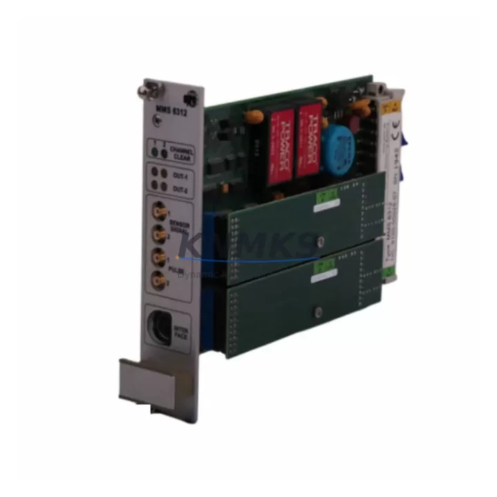
EPRO MMS6312 Migration-Ready Speed Monitor for Legacy Control Systems
The EPRO MMS6312 is a precision speed monitor module engineered for industrial facilities undertaking legacy control system migrations, discontinued module replacements, and control cabinet upgrades. As part of the MMS 6000 Series machinery protection platform, the MMS6312 delivers reliable shaft speed and overspeed detection in environments where aging infrastructure demands a drop-in compatible, firmware-verified replacement. Whether your facility is retiring obsolete Bently Nevada 3500 Series modules, decommissioning first-generation EPRO MMS 3000 units, or consolidating a mixed-vendor protection rack, the MMS6312 provides a validated migration path with minimal engineering rework.
Facilities managing rotating machinery — turbines, compressors, pumps, and fans — frequently encounter the challenge of sourcing discontinued speed monitoring modules that are no longer available through OEM channels. The MMS6312 addresses this gap directly. Its dual-channel speed input architecture supports magnetic pickup (MPU) and proximity probe signals, maintaining backward compatibility with existing field wiring and transducer installations. Before committing to a retrofit, engineers should verify terminal block pinout compatibility against the legacy module’s wiring diagram, confirm rack backplane slot assignments, and validate that the replacement module’s address configuration matches the existing PLC or DCS tag mapping.
Power supply capacity is a critical pre-installation checkpoint. The MMS6312 operates on a 24 VDC rail and draws within the standard MMS 6000 rack budget, but engineers replacing multiple modules simultaneously must audit the total rack current draw — particularly when the existing EPRO PR6423 proximity probes or CON021 signal conditioners remain in service on the same backplane. Confirm that the rack’s internal power distribution bus can sustain the combined load before energizing the upgraded configuration.
Migration Compatibility Table
| Parameter | MMS6312 (Current) | Legacy / Replaced Module | Migration Note |
|---|---|---|---|
| Module Type | Speed Monitor, Dual Channel | MMS 3000 / Bently 3500/25 | Verify channel count before swap |
| Input Signal | MPU / Proximity Probe | MPU / Eddy Current | Field wiring typically reusable |
| Power Supply | 24 VDC, rack-sourced | 24 VDC or 28 VDC (varies) | Audit rack bus capacity before install |
| Communication | Modbus RTU / PROFIBUS DP | Proprietary / RS-485 | Protocol mapping required for DCS/PLC |
| Backplane Interface | MMS 6000 Series rack slot | MMS 3000 rack (incompatible) | Rack replacement may be required |
| Module Address | DIP switch configurable | Jumper or fixed address | Match PLC tag address before power-on |
| Firmware Version | Confirm via EPRO configurator | Legacy firmware (no update path) | Download latest firmware pre-commissioning |
| HMI Screen Mapping | Tag-compatible with MMS 6000 | Custom HMI screens (legacy) | Update HMI faceplates post-swap |
| Installation Space | Standard MMS 6000 slot width | Varies by legacy platform | Measure cabinet DIN rail clearance |
| Support terms | support terms confirmed by quotation — All units pre-tested before dispatch | Covered from invoice date | |
Retrofit Planning for Existing Automation Systems
A successful MMS6312 retrofit begins well before the module arrives on-site. The migration plan should account for the full protection chain: from field transducers through signal conditioning to the control system. In a typical MMS 6000 rack, the MMS6312 operates alongside companion modules such as the MMS6110 vibration monitor and the MMS6220 temperature monitor, sharing a common backplane and power bus. Engineers should document the existing slot assignments for all active modules before removal to avoid address conflicts during recommissioning.
Terminal wiring is the most time-sensitive task during a live-system cutover. The MMS6312 uses a removable terminal block, which allows pre-wiring of the replacement module on the bench before the scheduled maintenance window. This approach — sometimes called a “hot-swap preparation” — significantly reduces the time the protection system is offline. When replacing modules connected to EPRO PR6423 proximity probes, verify that the probe gap voltage and sensitivity settings are re-entered into the new module’s configuration software, as these parameters are not stored on the backplane.
For facilities integrating the MMS6312 into a Siemens S7-300 or S7-400 PLC environment via PROFIBUS DP, the GSD file for the MMS 6000 Series must be imported into STEP 7 or TIA Portal before the network scan. Similarly, Modbus RTU integrations with Allen-Bradley ControlLogix or CompactLogix controllers require the correct function code mapping and register offset configuration in the MSG instruction. If the legacy system used a dedicated EPRO system monitor or a third-party SCADA via OPC, the new module’s tag names and scaling factors must be reconciled with the existing historian configuration to avoid data gaps in the process record.
I/O expansion during the retrofit window is a common opportunity. Facilities often use the planned downtime to add an MMS6824 I/O module or upgrade the rack’s communication gateway to support Ethernet/IP alongside the existing PROFIBUS segment. Planning these additions in advance — including DIN rail space, cable routing, and power budget — prevents secondary outages after the primary retrofit is complete.
Downtime Control During System Migration
Minimizing unplanned downtime during a speed monitor replacement requires a structured pre-outage checklist and a clear rollback procedure. Before the maintenance window opens, the existing PLC or DCS program logic should be exported and archived. For Siemens S7 platforms, this means saving the current project in STEP 7 or TIA Portal with all force tables and symbol tables intact. For Rockwell systems, an RSLogix 5000 or Studio 5000 project backup should be stored offline, including the I/O configuration tree that references the MMS6312’s Modbus register map.
During the physical swap, the protection system should be placed in bypass mode according to the site’s Management of Change (MOC) procedure. Bypassing individual channels rather than the entire rack reduces the risk window. Once the MMS6312 is seated and terminal wiring is confirmed, power the module and verify the green status LED before releasing the bypass. The module’s self-test routine runs automatically on power-up and will flag any input signal faults — typically caused by an open probe circuit or incorrect gap voltage — before the protection logic is re-enabled.
Post-installation, a functional verification test should confirm that the speed signal is correctly received at the PLC, that the overspeed trip setpoint is active, and that the HMI speed display matches the tachometer reading at the machine. If the legacy HMI screens referenced the old module’s tag names, update the screen bindings before returning the unit to service. Document the as-found and as-left configuration in the site’s maintenance management system (CMMS) to support future audits and spare parts planning. All MMS6312 units supplied by KNMKS are pre-tested under load conditions prior to dispatch, supporting a support terms confirmed by quotation from the invoice date.
Retrofit Support FAQ
Q1: Is the MMS6312 a direct drop-in replacement for MMS 3000 Series speed monitors?
The MMS6312 is designed for the MMS 6000 Series rack and is not mechanically or electrically interchangeable with MMS 3000 Series modules. A rack upgrade to the MMS 6000 platform is required. However, existing field wiring — including MPU cables and proximity probe leads — is typically reusable, reducing field labor costs significantly.
Q2: What commissioning steps are required after installing the MMS6312?
After physical installation, configure the module address via DIP switches to match the PLC tag assignment. Connect the EPRO configuration software via the module’s front-panel USB or RS-232 port to set the speed range, overspeed trip setpoint, and probe sensitivity. Verify the Modbus or PROFIBUS communication link from the PLC, confirm the speed signal reading at rated RPM, and test the trip relay output before releasing the bypass.
Q3: How do I confirm wiring compatibility before the maintenance window?
Request the MMS6312 terminal block pinout diagram and compare it against the legacy module’s wiring schedule. Pay particular attention to the MPU signal polarity, shield grounding point, and the relay output common terminal. Pre-wire the replacement module on the bench using the existing cable lengths to confirm reach before the outage begins.
Q4: What support terms and pre-shipment testing does KNMKS provide?
Every MMS6312 unit is functionally tested prior to dispatch, including input signal response, relay output operation, and communication link verification. A support terms confirmed by quotation is provided from the invoice date, covering manufacturing defects and module failure under normal operating conditions. In-stock units typically ship within 1–3 business days from Xiamen. Contact admin@knmks.com or +86 18359268345 for lead time confirmation and volume pricing.
© 2026 KNMKS. All rights reserved.
Original Source: https://knmks.com
Contact: admin@knmks.com | +86 18359268345
Product Identification
- Brand / Ecosystem
-
EPRO
Assorted Brands - Model / Series
-
MMS6312
Legacy Series - Product Family
- PLCs & Controllers
- Availability Status
- Available on request after model and quantity confirmation
- Inquiry Type
- B2B RFQ, replacement inquiry and project spare-part request
- Pre-Quote Check
- Exact SKU, brand, series, quantity, nameplate photos and destination country are checked before quotation
System Path
Where this product fits in the KNMKS automation structure.
Specification & Inquiry Focus
- Control platform
- PLC, PAC and modular controllers
- Common needs
- CPU, rack, power and I/O expansion
- Project support
- Replacement, cabinet build and maintenance
Buyer Confirmation
Information KNMKS checks before replying.
- Exact model
- MMS6312
- Brand / ecosystem
- EPRO
- Product family
- PLCs & Controllers
- Application note
- Replacement, maintenance, project build or spare-part list
- Useful photos
- Nameplate, installed unit, cabinet layout or connector side
- Delivery details
- Quantity, destination country and target schedule
Document Support
Files and notes can be confirmed during quotation.
- Product photos or nameplate confirmation when available
- Packing and delivery notes before quotation confirmation
- Support scope and delivery terms confirmed per inquiry
- Export document coordination for qualified B2B requests
Inquiry Support
- Model cross-checking before quotation
- CPU, power, rack and expansion module matching
- Support for replacement and project inquiry
What to Send Us
- Brand and exact model number: EPRO MMS6312
- Quantity and required delivery time
- Application, replacement requirement or nameplate photo
- Destination country and shipping preference
RFQ Preparation
This is a product inquiry page built for RFQ communication.
Fast Model Check
Send this model to KNMKS for confirmation.
Include quantity, destination country and photos if this is a maintenance replacement. The inquiry will be saved with a reference number after submission.
Brand & Compatibility Note
KNMKS displays automation product information for well-known industrial brand ecosystems and compatible replacement references. Brand names are used for product identification and compatibility reference only; final availability and commercial terms are confirmed per quotation.
 Manufacturing
 Machine Tools
 Packaging
 Energy & Power
 HMI & Displays
 Servo Systems
 Variable Frequency Drives
 Sensors