
Overview
Bently Nevada 330194-17-25-15-00 Migration-Ready Proximity Probe for Legacy Control Systems
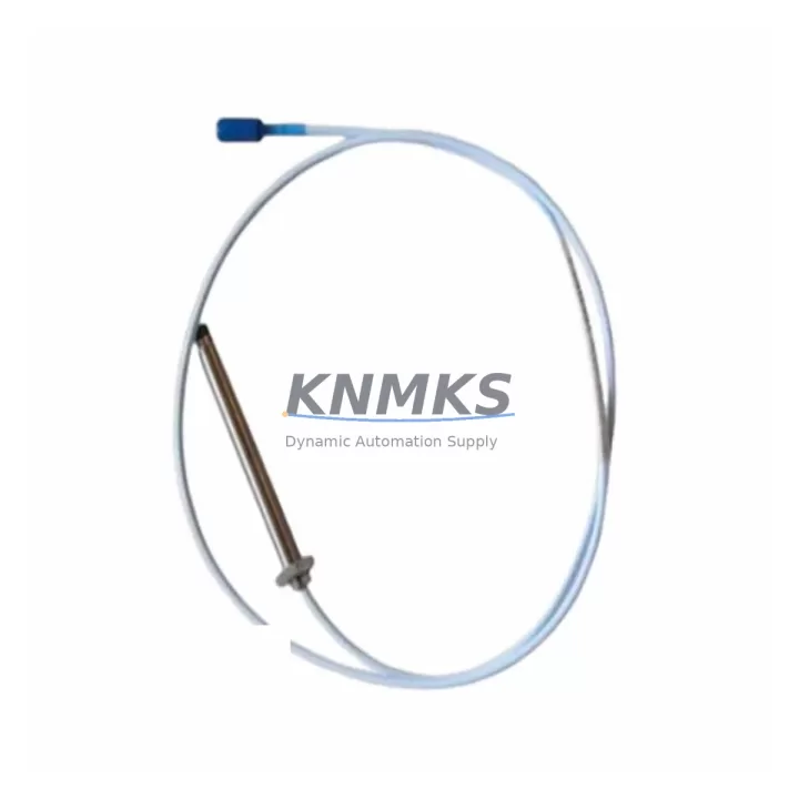
The Bently Nevada 330194-17-25-15-00 is a 25mm proximity probe engineered for the 3300 XL Series continuous vibration monitoring platform. As legacy Bently Nevada 3300 systems approach end-of-support milestones, plant engineers and reliability teams face increasing pressure to source verified replacement components that preserve existing wiring infrastructure, conduit routing, and monitor channel configurations without triggering a full-system overhaul. This probe is a direct, drop-in replacement that maintains signal chain integrity across the complete 3300 XL measurement loop.
The 330194-17-25-15-00 features a 25mm tip diameter, 5-metre armoured extension cable, and a standard -15 VDC bias voltage output compatible with the Bently Nevada 3300 XL 8mm and 11mm monitor modules. Its reverse-mount thread configuration and 1-metre probe cable length make it suitable for tight bearing housing installations on steam turbines, compressors, pumps, and gearboxes where radial shaft displacement measurement is critical to machinery protection logic.
When planning a retrofit around this probe, engineers must verify the existing Bently Nevada 3500/42M or 3300 XL monitor card slot assignment, confirm the proximitor/extension cable system pairing (the 330180 Series proximitor is the standard companion for this probe family), and validate that the gap voltage at installation falls within the linear range of -10 VDC to -18 VDC. Incorrect gap setting is the leading cause of false trip events during commissioning after a probe swap.
Migration Compatibility Table
| Parameter | 330194-17-25-15-00 Specification | Retrofit / Replacement Notes |
|---|---|---|
| Probe Tip Diameter | 25 mm | Verify bearing housing bore clearance before installation |
| Probe Cable Length | 1 metre (3.3 ft) | Match to existing conduit run; extension cable makes up remaining distance |
| Extension Cable Length | 5 metres (16.4 ft) | Total system cable = probe + extension; must match proximitor calibration |
| Bias Voltage | -15 VDC nominal | Compatible with 3300 XL and 3500 Series monitor power supply rails |
| Compatible Monitor | 3300 XL 8mm / 11mm, 3500/42M | Confirm channel card firmware version supports 25mm probe sensitivity factor |
| Compatible Proximitor | 330180 Series | Do not mix proximitor series; recalibrate after any proximitor change |
| Thread Configuration | Reverse-mount (standard) | Confirm existing probe boss thread type before ordering |
| Installation Environment | -35°C to +177°C | Suitable for high-temperature bearing housings on steam turbines |
| Communication / Signal | Analogue eddy-current output | No protocol migration required; direct signal wire replacement |
| Support terms | 12 Months | Covers manufacturing defects; includes pre-shipment functional test report |
Retrofit Planning for Existing Automation Systems
A successful retrofit of the 330194-17-25-15-00 into an operating machinery protection system requires a structured pre-outage audit. Begin by documenting the existing probe serial number, proximitor model (typically a 330180-51-00 or 330180-91-00 for 5-metre cable systems), and the current gap voltage reading logged by the 3300 XL monitor. This baseline allows the commissioning technician to verify that the replacement probe achieves the same gap voltage at the same physical air gap, confirming that the eddy-current sensitivity factor is consistent between the old and new units.
For plants running a Bently Nevada 3500 rack alongside legacy 3300 XL panels, the 3500/42M Proximitor I/O Module accepts the same probe-and-extension cable assembly, making the 330194-17-25-15-00 a viable interim spare during a phased migration from 3300 XL to 3500 architecture. During this transition, the 3500/20 Power Supply Module must be confirmed to supply adequate -24 VDC to the proximitor circuit, and the 3500/22M Transient Data Interface should be checked for channel mapping consistency if the plant historian is configured to trend shaft displacement data.
Where control cabinet space is constrained, engineers should audit the DIN rail layout and verify that the replacement probe cable routing does not introduce ground loops through the cabinet backplane. Signal isolation between the proximity probe circuit and the PLC analogue input card — often a third-party module such as a Phoenix Contact MACX or Pepperl+Fuchs KFD2 series signal conditioner — must be maintained to prevent common-mode noise from corrupting the vibration measurement. If the plant uses a Rockwell Automation ControlLogix or CompactLogix platform for supervisory control, the analogue input module (1756-IF16 or 1769-IF4) receiving the 4–20 mA converted signal should be re-ranged in RSLogix 5000 / Studio 5000 after the probe swap to reflect the new calibration constants.
HMI faceplate updates on a GE iFIX, Wonderware InTouch, or Ignition SCADA screen should be scheduled as part of the same maintenance window. Tag scaling for the shaft displacement trend display must be verified against the new probe’s sensitivity specification (typically 7.87 V/mm for a 25mm probe) to prevent misleading alarm threshold displays during the first post-commissioning run.
Downtime Control During System Migration
Minimising unplanned downtime during a proximity probe replacement on a running machinery protection system requires a pre-staged swap kit and a clearly defined bypass procedure. Before the outage window opens, the replacement 330194-17-25-15-00, the companion 330180 Series proximitor, and all required hand tools should be staged at the work location. The 3300 XL or 3500 monitor channel should be placed in bypass mode — not defeated — so that the machinery protection system continues to monitor all other channels while the affected channel is being serviced.
Original program logic in the safety PLC or machinery protection controller must not be modified during the probe swap. The bypass state should be documented in the permit-to-work system with a defined time limit. Once the replacement probe is installed and the gap voltage is confirmed within the -10 VDC to -18 VDC linear range, the channel bypass is removed and the monitor is returned to normal protection mode. A 30-minute observation period at operating speed is recommended before closing the work permit, during which the shaft displacement trend, 1X and 2X vibration vectors, and alarm setpoint margins should all be verified against the pre-outage baseline.
For plants with redundant probe installations (X-Y probe pairs), the second probe channel remains active throughout the swap, providing continuous shaft position data to the protection system and eliminating the risk of a spurious trip during the maintenance activity. This redundancy architecture is standard on critical rotating equipment such as high-pressure steam turbines, centrifugal compressors, and boiler feed pumps where a false trip carries significant production cost.
Retrofit Support FAQ
Q1: Is the 330194-17-25-15-00 a direct replacement for the 330194-17-25-15-CN or other regional variants?
The -CN suffix denotes a China-market certification variant. The core eddy-current probe specification is identical; however, the -CN variant may carry additional CCC or SIL certification markings required by certain Chinese plant standards. Confirm with your site compliance team whether the standard -00 suffix unit satisfies local regulatory requirements before installation. Both variants use the same 330180 Series proximitor and are electrically interchangeable within the 3300 XL measurement loop.
Q2: What commissioning steps are required after installing the replacement probe?
After mechanical installation, set the probe gap to achieve a bias voltage of -10 VDC to -12 VDC (mid-linear range) using a calibrated DC voltmeter at the proximitor output terminals. Record the gap distance (typically 1.0 mm to 1.5 mm for a 25mm probe). Verify the monitor channel clears any latched alerts, confirm the OK relay is energised, and log the as-found and as-left gap voltages in the maintenance management system. No firmware changes to the 3300 XL or 3500 monitor are required for a like-for-like probe replacement.
Q3: Can this probe be used with a Bently Nevada 3500/42M monitor without reconfiguring the rack?
Yes. The 3500/42M Proximitor I/O Module is designed to accept the same 330194 Series probe and 330180 Series proximitor combination used in 3300 XL systems. The rack configuration in System 1 software should be reviewed to confirm the channel sensitivity factor matches the 25mm probe specification. No hardware changes to the 3500 rack backplane or power supply are required, provided the existing cable lengths are within the proximitor’s calibrated range.
Q4: What does the support terms confirmed by quotation cover, and is a pre-shipment test report available?
All units are covered by a support terms confirmed by quotation against manufacturing defects from the date of shipment. Each probe undergoes a pre-shipment functional test verifying gap voltage linearity, cable continuity, and connector integrity. A test report is available upon request and can be provided with the shipment documentation. Replacement or refund is offered for any unit that fails to meet the published specification within the confirmed support period. Contact admin@knmks.com for support requests or to request a test report prior to order placement.
© 2026 KNMKS. All rights reserved.
Original Source: https://knmks.com
Contact: admin@knmks.com | +86 18359268345
Product Identification
- Brand / Ecosystem
-
BENTLY NEVADA
Bently Nevada - Model / Series
-
330194-17-25-15-00
Bently Nevada 3300 XL / 3301 Series - Product Family
- Sensors
- Availability Status
- Available on request after model and quantity confirmation
- Inquiry Type
- B2B RFQ, replacement inquiry and project spare-part request
- Pre-Quote Check
- Exact SKU, brand, series, quantity, nameplate photos and destination country are checked before quotation
System Path
Where this product fits in the KNMKS automation structure.
Specification & Inquiry Focus
- Sensor range
- Photoelectric, proximity and process sensors
- Common needs
- Output type, distance and connector
- Project support
- Machine detection and replacement inquiry
Buyer Confirmation
Information KNMKS checks before replying.
- Exact model
- 330194-17-25-15-00
- Brand / ecosystem
- BENTLY NEVADA
- Product family
- Sensors
- Application note
- Replacement, maintenance, project build or spare-part list
- Useful photos
- Nameplate, installed unit, cabinet layout or connector side
- Delivery details
- Quantity, destination country and target schedule
Document Support
Files and notes can be confirmed during quotation.
- Product photos or nameplate confirmation when available
- Packing and delivery notes before quotation confirmation
- Support scope and delivery terms confirmed per inquiry
- Export document coordination for qualified B2B requests
Inquiry Support
- NPN/PNP, analog and digital output checking
- Connector and cable compatibility review
- Fast inquiry support for maintenance teams
What to Send Us
- Brand and exact model number: BENTLY NEVADA 330194-17-25-15-00
- Quantity and required delivery time
- Application, replacement requirement or nameplate photo
- Destination country and shipping preference
RFQ Preparation
This is a product inquiry page built for RFQ communication.
Fast Model Check
Send this model to KNMKS for confirmation.
Include quantity, destination country and photos if this is a maintenance replacement. The inquiry will be saved with a reference number after submission.
Brand & Compatibility Note
KNMKS displays automation product information for well-known industrial brand ecosystems and compatible replacement references. Brand names are used for product identification and compatibility reference only; final availability and commercial terms are confirmed per quotation.
 Manufacturing
 Machine Tools
 Packaging
 Energy & Power



 PLCs & Controllers
 HMI & Displays
 Servo Systems
 Variable Frequency Drives