
Overview
Bently Nevada 330130-080-11-00 Migration-Ready Extension Cable: Legacy System Migration and Compatible Upgrade
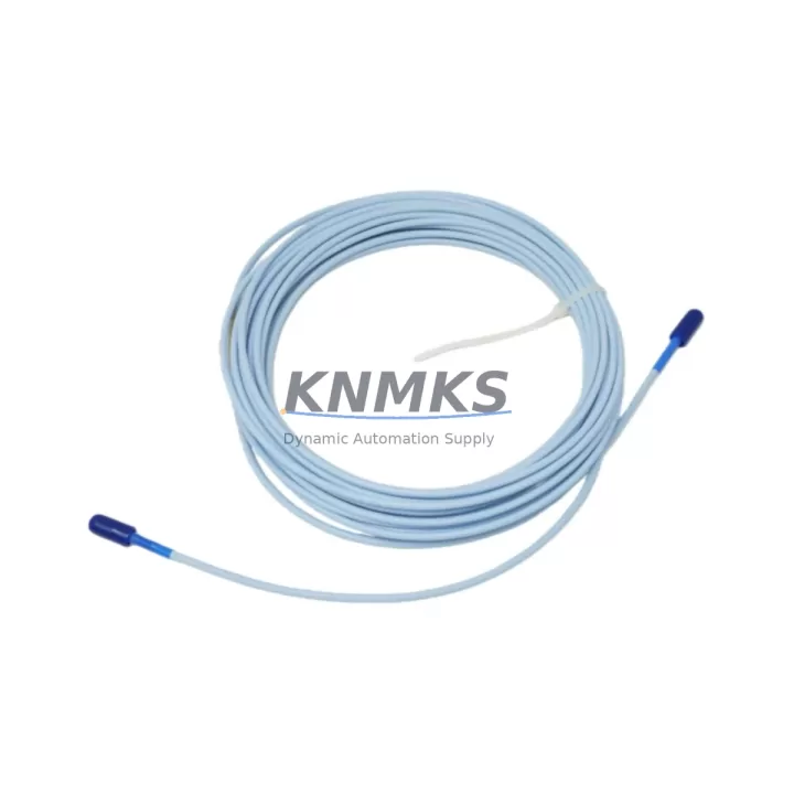
The Bently Nevada 330130-080-11-00 is an 8-meter (26.2 ft) proximity extension cable engineered for the 3300 XL Proximitor® Sensor system. Designed to bridge the gap between legacy vibration monitoring installations and modern control architectures, this cable is a direct, migration-ready replacement for aging or discontinued extension cable assemblies used in rotating machinery protection systems across energy, petrochemical, and heavy manufacturing sectors.
When a plant engineer initiates a retrofit of an existing Bently Nevada 3300 series monitoring loop, the extension cable is often the first component to be evaluated. The 330130-080-11-00 maintains full signal integrity between the proximity probe and the Proximitor sensor, preserving the 200 mV/mil output characteristic required by downstream monitors such as the 3300/16 Dual Vibration Monitor or the 3500/42M Proximitor®/Seismic Monitor. Confirming cable length compatibility with the existing probe-to-Proximitor gap is a critical pre-installation step: the total system cable length — including the armored extension and the probe integral cable — must remain within the calibrated range specified for the transducer system.
Before installation, technicians should verify terminal wiring continuity at both the junction box and the monitor I/O terminal block. The 330130-080-11-00 uses standard BNC-to-BNC connectors with a coaxial shielded construction, compatible with the 3300 XL Proximitor housing. When replacing cables in an existing panel, confirm that the cable routing does not introduce ground loops — particularly in installations where the 3300/20-02-01-00 Power Supply Module or a shared DC bus feeds multiple Proximitor channels. Shield grounding should follow the single-point grounding scheme documented in the original system design.
For plants migrating from older 3300 series racks to the 3500 series rack-based architecture, the 330130-080-11-00 remains compatible provided the Proximitor sensor model is unchanged. If the migration path includes replacing the Proximitor with a newer 3300 XL Proximitor (e.g., 330180-X1-05), the extension cable specification must be re-validated against the new sensor’s cable length requirements. In parallel, the 3500 rack backplane slot assignment and module address configuration should be updated in the System 1 Evolution software to reflect the new channel mapping before the system is brought back online.
HMI screen updates are frequently overlooked during cable-level retrofits. If the plant uses a GE iFIX, Wonderware, or Ignition SCADA platform connected to the 3500 rack via Modbus TCP or OPC-DA, the tag database should be audited to confirm that vibration channel tags remain correctly mapped after any rack reconfiguration. A mismatch between the physical channel and the SCADA tag can result in false alarms or missed trips during the post-retrofit commissioning phase.
Downtime planning for a proximity extension cable replacement is typically minimal — most experienced technicians complete the swap within a two-hour maintenance window — but the process should include a pre-work checklist covering: cable continuity test, Proximitor DC bias voltage verification (nominally −10 VDC to −18 VDC at the monitor input), gap voltage confirmation at the probe tip, and a channel functional test using the 3500 rack’s built-in self-test or a portable Bently Nevada field calibrator. All replaced cables should be tagged and retained for post-maintenance documentation.
Migration Compatibility Table
| Parameter | 330130-080-11-00 Specification | Retrofit / Migration Notes |
|---|---|---|
| Cable Length | 8 meters (26.2 ft) | Verify total system cable length within calibrated range |
| Connector Type | BNC coaxial, shielded | Compatible with 3300 XL Proximitor housing; confirm mating connector condition |
| Signal Output | 200 mV/mil (supports 3300 XL system) | Maintain output spec when migrating to 3500 series monitors |
| Communication Compatibility | Analog signal (DC bias loop) | No protocol change required; verify Modbus/OPC tag mapping post-retrofit |
| Backplane / Rack Interface | N/A (field cable) | Confirm 3500 rack slot assignment and module address after rack migration |
| Power Supply Compatibility | Powered via Proximitor sensor | Verify DC bus capacity if sharing with 3300/20-02-01-00 Power Supply Module |
| Installation Space | Standard conduit / cable tray routing | Confirm conduit fill ratio and bend radius in existing cable tray |
| Firmware Dependency | None (passive cable assembly) | No firmware update required; validate monitor firmware post rack migration |
| Replacement Relationship | Direct replacement for 330130-080-11-00 | Cross-reference with 330130-080-00-00 (non-armored) if armoring not required |
| Support terms | support terms confirmed by quotation — covers manufacturing defects and signal integrity failure under normal operating conditions | |
Retrofit Planning for Existing Automation Systems
A successful proximity extension cable retrofit requires a systems-level view of the entire vibration monitoring loop. The 330130-080-11-00 operates as part of a signal chain that typically includes the 3300 XL Proximitor sensor, the proximity probe (such as the 330101-00-06-10-02-00 or 330104 series), and the monitor module installed in the 3500 rack. When planning the retrofit, engineers should map each component in the loop and confirm that no adjacent modules — including the 3500/22M Transient Data Interface or the 3500/15 Power Supply — will be affected by the cable replacement activity.
In control cabinets where space is constrained, the cable routing path should be pre-planned before the maintenance window begins. The 330130-080-11-00’s 8-meter length is well-suited for most turbine bearing pedestals and compressor skid installations, but in cases where the junction box is located at an unusual distance, a 330130-050-11-00 (5-meter) or 330130-120-11-00 (12-meter) variant should be evaluated. Confirm that the replacement cable’s armored jacket is compatible with the existing conduit fittings and cable gland specifications at the junction box entry point.
For installations that include signal isolators between the Proximitor output and the DCS analog input card, verify that the isolator’s input impedance does not load the Proximitor output beyond its specified drive capability. Signal isolation modules from third-party suppliers are common in older installations and may require recalibration after the cable is replaced if the loop impedance changes. Similarly, if the plant uses a 3300/46M or 3500/46M Speed Monitor in the same rack, confirm that the speed channel wiring is undisturbed during the extension cable replacement to avoid nuisance trips on the overspeed protection circuit.
Downtime Control During System Migration
Minimizing unplanned downtime during a proximity extension cable replacement begins with pre-work preparation. Before the maintenance window opens, the technician should have the replacement 330130-080-11-00 bench-tested for continuity and insulation resistance, with the Proximitor sensor DC bias voltage pre-verified using a calibrated multimeter. The original program logic in the 3500 rack should be backed up using System 1 Evolution or the rack’s configuration upload utility, ensuring that all channel setpoints, alarm thresholds, and trip multipliers are preserved.
During the replacement, the affected channel should be placed in bypass mode at the monitor to prevent a spurious trip from propagating to the turbine control system or the ESD (Emergency Shutdown) logic. After the new cable is installed and the Proximitor gap voltage is confirmed within the ±0.5 VDC tolerance of the original calibration, the bypass should be removed and the channel returned to normal monitoring mode. A post-installation functional test — including a simulated vibration input using a calibrated shaker or a gap simulation resistor — should be completed before the maintenance window is closed.
For plants operating under IEC 61511 or ISA-84 functional safety requirements, the post-replacement proof test record should be updated to reflect the cable replacement date, the technician’s identification, and the as-found / as-left gap voltage readings. This documentation supports the plant’s safety instrumented system (SIS) audit trail and ensures compliance with the required proof test interval for the vibration monitoring loop.
Retrofit Support FAQ
Q1: Is the 330130-080-11-00 a direct replacement for my existing Bently Nevada extension cable?
Yes. The 330130-080-11-00 is a direct, pin-compatible replacement for the same SKU in the 3300 XL Proximitor system. If your existing cable is a different length variant (e.g., 330130-050-11-00 or 330130-120-11-00), confirm that the 8-meter length is appropriate for your installation before ordering. All units are pre-tested for signal continuity and insulation resistance prior to shipment.
Q2: What commissioning steps are required after installing the replacement cable?
After installation, verify the Proximitor DC bias voltage at the monitor input terminal (nominally −10 VDC to −18 VDC), confirm the probe gap voltage is within the calibrated range, and perform a channel functional test. If the installation is part of a 3500 rack migration, also confirm the rack module address configuration and SCADA tag mapping before returning the channel to service.
Q3: Can this cable be used with both the 3300 series and 3500 series Bently Nevada racks?
Yes, provided the Proximitor sensor model is unchanged. The extension cable is a passive assembly and is compatible with any Proximitor sensor that accepts a standard BNC coaxial extension cable within the specified total cable length range. Confirm the Proximitor model’s cable length specification before use in a 3500 series migration.
Q4: What is the support terms coverage and what does in-stock availability mean for my project?
All 330130-080-11-00 units supplied by KNMKS carry a support terms confirmed by quotation covering manufacturing defects and signal integrity failure under normal operating conditions. Units are available from in-stock inventory and can be shipped within 1–3 business days, supporting urgent replacement and planned maintenance schedules alike. Contact admin@knmks.com or +86 18359268345 for lead time confirmation and volume pricing.
© 2026 KNMKS. All rights reserved.
Original Source: https://knmks.com
Contact: admin@knmks.com | +86 18359268345
Product Identification
- Brand / Ecosystem
-
Bently Nevada
Bently Nevada - Model / Series
-
330130-080-11-00
Bently Nevada 3300 XL / 3301 Series - Product Family
- Cables & Connectors
- Availability Status
- Available on request after model and quantity confirmation
- Inquiry Type
- B2B RFQ, replacement inquiry and project spare-part request
- Pre-Quote Check
- Exact SKU, brand, series, quantity, nameplate photos and destination country are checked before quotation
System Path
Where this product fits in the KNMKS automation structure.
Specification & Inquiry Focus
- Cable range
- Sensor, servo, network and circular connectors
- Common needs
- Length, pin count, shielding and plug type
- Project support
- Machine wiring and installation kits
Buyer Confirmation
Information KNMKS checks before replying.
- Exact model
- 330130-080-11-00
- Brand / ecosystem
- Bently Nevada
- Product family
- Cables & Connectors
- Application note
- Replacement, maintenance, project build or spare-part list
- Useful photos
- Nameplate, installed unit, cabinet layout or connector side
- Delivery details
- Quantity, destination country and target schedule
Document Support
Files and notes can be confirmed during quotation.
- Product photos or nameplate confirmation when available
- Packing and delivery notes before quotation confirmation
- Support scope and delivery terms confirmed per inquiry
- Export document coordination for qualified B2B requests
Inquiry Support
- Cable length and connector type confirmation
- Servo, sensor and network cable inquiry
- Accessory kits for installation teams
What to Send Us
- Brand and exact model number: Bently Nevada 330130-080-11-00
- Quantity and required delivery time
- Application, replacement requirement or nameplate photo
- Destination country and shipping preference
RFQ Preparation
This is a product inquiry page built for RFQ communication.
Fast Model Check
Send this model to KNMKS for confirmation.
Include quantity, destination country and photos if this is a maintenance replacement. The inquiry will be saved with a reference number after submission.
Brand & Compatibility Note
KNMKS displays automation product information for well-known industrial brand ecosystems and compatible replacement references. Brand names are used for product identification and compatibility reference only; final availability and commercial terms are confirmed per quotation.
 Manufacturing
 Machine Tools
 Packaging
 Energy & Power
 PLCs & Controllers
 HMI & Displays
 Servo Systems
 Variable Frequency Drives