
Overview
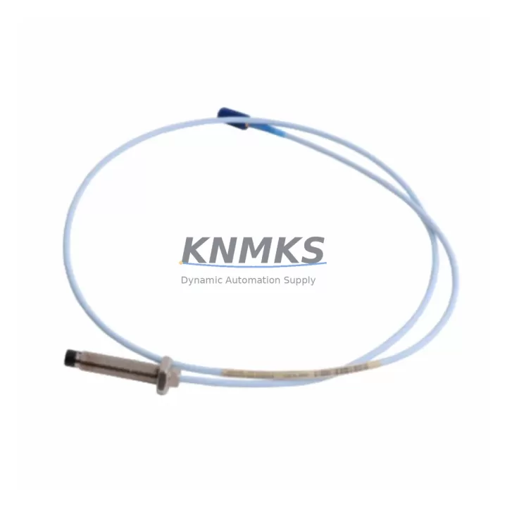
Bently Nevada 330130-080-01-05 Migration-Ready 8m Extension Cable: Legacy System Retrofit & Compatible Upgrade
The Bently Nevada 330130-080-01-05 is an 8-meter coaxial extension cable engineered for the 3300 XL proximity transducer system — one of the most widely deployed vibration monitoring platforms in rotating machinery protection. As legacy 3300 XL installations approach end-of-support cycles, this cable remains a critical spare part for facilities executing phased migration strategies, control cabinet upgrades, and machinery protection system modernization without full platform replacement.
This extension cable connects the 3300 XL proximity probe to its paired proximitor/oscillator module, maintaining the signal integrity required for accurate shaft displacement and vibration measurement. When replacing a failed or degraded cable in an operating plant, the 330130-080-01-05 provides a direct, pin-compatible substitution that eliminates the need to reconfigure the proximitor module, reroute conduit, or modify the existing terminal block wiring in the junction box.
For facilities managing a mixed fleet of Bently Nevada 3300 XL and 3500 series monitors, the cable selection process must account for probe series compatibility, proximitor model, and the total system scale factor. The 330130-080-01-05 is rated for use with standard 3300 XL proximitor/oscillator modules and is not interchangeable with 3500/42M or 3500/45 monitor inputs without verifying the combined probe-cable-proximitor scale factor against the monitor’s configured gap voltage range. Confirm the existing proximitor model — such as the 330180 or 330101 series — before installation to avoid measurement offset errors that could trigger false alarms or mask real machinery faults.
During retrofit planning, engineers should also verify the cable routing path for physical clearance, bend radius compliance, and conduit fill ratio. The 8-meter length of the 330130-080-01-05 suits most standard turbine pedestal and compressor skid installations where the junction box is located within the machinery guard perimeter. For installations requiring longer cable runs, the 330130-085-01-05 (9m) or 330130-090-01-05 (10m) variants should be evaluated as alternatives within the same cable family.
When integrating this cable into a broader machinery protection upgrade, the associated 3300 XL proximitor module, the 3300/16 or 3300/20 monitor rack, and the 3500/22M transient data interface should all be inspected for firmware compatibility and channel configuration. If the site is migrating from a standalone 3300 XL rack to a 3500 series integrated monitoring system, the extension cable and probe assembly may be reused provided the scale factor and gap voltage specifications are re-validated against the new monitor’s input card configuration. The 3500 series rack accepts the same probe-cable-proximitor assemblies but requires channel-by-channel reconfiguration through the System 1 software or the rack’s front-panel keypad.
Downtime risk during cable replacement is low when a pre-tested spare assembly is available on-site. The 330130-080-01-05 should be stored in its original packaging in a climate-controlled environment to preserve the coaxial connector integrity and prevent oxidation of the BNC-style terminations. Before installation, inspect both connectors for pin straightness, thread condition, and contamination. Torque the connectors to the manufacturer’s specification — typically finger-tight plus one-quarter turn — to ensure consistent contact resistance and prevent signal noise that could be misinterpreted as shaft vibration by the monitor.
Migration Compatibility Table
| Parameter | Detail |
|---|---|
| SKU / Part Number | 330130-080-01-05 |
| Cable Length | 8 meters (26.2 ft) |
| Compatible System | Bently Nevada 3300 XL Proximity Transducer System |
| Compatible Proximitor Series | 330180, 330101 (verify scale factor before installation) |
| Connector Type | Coaxial BNC-style, both ends |
| Installation Requirement | Verify total system scale factor; confirm gap voltage range on monitor |
| 3500 Series Cross-Compatibility | Conditional — requires scale factor re-validation with 3500/42M or 3500/45 |
| Commissioning Check | Gap voltage, scale factor, alarm setpoint verification via System 1 or keypad |
| Retrofit Risk Level | Low — direct replacement with no wiring modification required |
| Support terms | 12 months from date of shipment |
| Origin | USA |
Retrofit Planning for Existing Automation Systems
A successful cable replacement within a 3300 XL machinery protection system requires coordination across several interdependent components. The proximitor/oscillator module — typically a 330180-X1-05 or 330101-00-06 — must be confirmed operational before the cable is replaced, as a failed proximitor will produce the same gap voltage symptoms as a damaged cable. Use a calibrated oscilloscope or the monitor’s built-in diagnostic display to isolate the fault to the cable before committing to replacement.
The 3300/16 or 3300/20 monitor rack housing the channel card should be inspected for alarm inhibit status before disconnecting the cable. Most 3300 XL racks support a maintenance bypass mode that suppresses trip outputs during cable work, preventing spurious machinery shutdowns. Confirm the bypass is active and logged in the site’s permit-to-work system before breaking the coaxial connection.
For sites also upgrading the junction box terminal blocks or replacing the field wiring conduit, the cable swap is an efficient opportunity to inspect the probe body — such as a 330104-00-06 or 330105-02-12 proximity probe — for tip damage, thread wear, and gap setting. The probe gap should be re-verified with a digital voltmeter after the new cable is installed, targeting the nominal gap voltage specified on the proximitor label, typically −10 VDC ±0.5 V for standard 200 mV/mil systems.
If the site is also deploying a new 3500/22M transient data interface or upgrading the System 1 condition monitoring software, the cable replacement can be coordinated with the software reconfiguration outage to minimize total downtime. The 3500 rack’s I/O module and the associated Ethernet communication card should be staged and pre-configured before the maintenance window to reduce on-site commissioning time.
Downtime Control During System Migration
Minimizing unplanned downtime during a 3300 XL cable replacement requires pre-staging the 330130-080-01-05 as a verified spare, confirming the replacement procedure with the OEM service manual, and coordinating the work with the site’s planned maintenance schedule. The following practices reduce migration risk:
- Pre-test the spare cable on a bench proximitor setup before the maintenance window to confirm continuity, insulation resistance, and connector integrity.
- Activate monitor bypass mode on the 3300/16 or 3300/20 rack before disconnecting the cable to suppress trip outputs and protect the machinery protection logic.
- Document the existing gap voltage on the channel display before removal so the post-installation gap can be restored to the same setpoint without re-entering the alarm configuration.
- Preserve the original program logic in the System 1 database or the rack’s non-volatile memory — cable replacement does not affect stored configurations, but a rack power cycle during the work may reset volatile alarm inhibit states.
- Verify communication link continuity on the Modbus or Ethernet channel after installation to confirm the monitor is reporting correctly to the DCS or SCADA historian.
- Complete a post-installation functional test covering gap voltage, vibration alarm response, and trip relay output before releasing the bypass and returning the machinery to service.
With a pre-tested spare and a structured commissioning checklist, cable replacement on a 3300 XL channel can typically be completed within a two-hour planned outage window, including gap verification and alarm function testing.
Retrofit Support FAQ
Q1: Is the 330130-080-01-05 a direct replacement for my existing 3300 XL extension cable?
Yes, provided your existing cable is from the 330130 series and your proximitor model is compatible (330180 or 330101 series). Verify the cable length matches your installation — the -080 suffix denotes 8 meters. If your current cable is a different length, select the corresponding variant from the 330130 series.
Q2: Can I use this cable with a Bently Nevada 3500 series monitor?
Conditionally. The 330130-080-01-05 can be used with 3500 series monitors if the combined probe-cable-proximitor scale factor is re-validated against the monitor’s configured input range. Do not assume direct compatibility without confirming the gap voltage and scale factor with the 3500/42M or 3500/45 channel card documentation.
Q3: What commissioning checks are required after installation?
After installing the 330130-080-01-05, verify the gap voltage at the monitor display or via System 1 software, confirm the vibration alarm setpoints are active, test the trip relay output using the monitor’s test function, and restore the maintenance bypass to normal operating mode. Log all readings in the site’s maintenance record.
Q4: What is the support terms and availability for this part?
The 330130-080-01-05 is supplied with a support terms confirmed by quotation from the date of shipment, covering manufacturing defects and connector integrity. Stock is maintained for immediate dispatch. Contact our team for lead time confirmation and volume pricing for multi-unit spare parts programs.
© 2026 KNMKS. All rights reserved.
Original Source: https://knmks.com
Contact: admin@knmks.com | +86 18359268345
Product Identification
- Brand / Ecosystem
-
Bently Nevada
Bently Nevada - Model / Series
-
330130-080-01-05
Bently Nevada 3300 XL / 3301 Series - Product Family
- Cables & Connectors
- Availability Status
- Available on request after model and quantity confirmation
- Inquiry Type
- B2B RFQ, replacement inquiry and project spare-part request
- Pre-Quote Check
- Exact SKU, brand, series, quantity, nameplate photos and destination country are checked before quotation
System Path
Where this product fits in the KNMKS automation structure.
Specification & Inquiry Focus
- Cable range
- Sensor, servo, network and circular connectors
- Common needs
- Length, pin count, shielding and plug type
- Project support
- Machine wiring and installation kits
Buyer Confirmation
Information KNMKS checks before replying.
- Exact model
- 330130-080-01-05
- Brand / ecosystem
- Bently Nevada
- Product family
- Cables & Connectors
- Application note
- Replacement, maintenance, project build or spare-part list
- Useful photos
- Nameplate, installed unit, cabinet layout or connector side
- Delivery details
- Quantity, destination country and target schedule
Document Support
Files and notes can be confirmed during quotation.
- Product photos or nameplate confirmation when available
- Packing and delivery notes before quotation confirmation
- Support scope and delivery terms confirmed per inquiry
- Export document coordination for qualified B2B requests
Inquiry Support
- Cable length and connector type confirmation
- Servo, sensor and network cable inquiry
- Accessory kits for installation teams
What to Send Us
- Brand and exact model number: Bently Nevada 330130-080-01-05
- Quantity and required delivery time
- Application, replacement requirement or nameplate photo
- Destination country and shipping preference
RFQ Preparation
This is a product inquiry page built for RFQ communication.
Fast Model Check
Send this model to KNMKS for confirmation.
Include quantity, destination country and photos if this is a maintenance replacement. The inquiry will be saved with a reference number after submission.
Brand & Compatibility Note
KNMKS displays automation product information for well-known industrial brand ecosystems and compatible replacement references. Brand names are used for product identification and compatibility reference only; final availability and commercial terms are confirmed per quotation.
 Manufacturing
 Machine Tools
 Packaging
 Energy & Power
 PLCs & Controllers
 HMI & Displays
 Servo Systems
 Variable Frequency Drives