
Overview
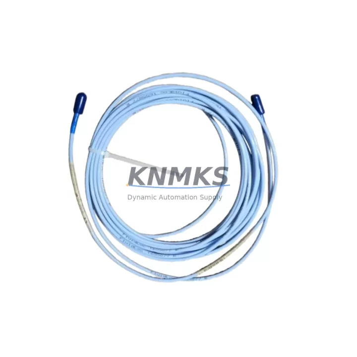
Bently Nevada 330130-075-10-05 Maintenance-Proven Spare Part for Factory Uptime
The Bently Nevada 330130-075-10-05 is a 7.5-metre proximity extension cable engineered for the 3300 XL continuous vibration monitoring system — one of the most widely deployed machinery protection platforms in rotating equipment applications across power generation, petrochemical, oil & gas, and heavy manufacturing. As a direct OEM-compatible spare, this cable forms the critical signal path between the proximity probe and the Bently Nevada 3300 XL proximitor/driver, transmitting raw eddy-current displacement signals with the precision required for shaft vibration, axial position, and differential expansion measurements.
For maintenance engineers managing turbine trains, compressor strings, or pump arrays, the extension cable is often the first component to degrade in high-temperature, high-vibration environments. Connector fatigue, insulation breakdown, and shield continuity loss are common failure modes that introduce noise into the vibration channel — triggering nuisance trips or, worse, masking genuine machinery faults. Stocking the 330130-075-10-05 as a certified spare eliminates the diagnostic ambiguity and reduces mean time to repair (MTTR) when a cable fault is isolated during routine point checks or emergency fault isolation.
This unit ships fully tested, with connector integrity verified and cable continuity confirmed prior to dispatch. Each unit carries a support terms confirmed by quotation covering manufacturing defects and signal integrity performance under normal operating conditions.
Spare Maintenance Table
| Parameter | Specification |
|---|---|
| Part Number | 330130-075-10-05 |
| Brand | Bently Nevada |
| Series | 3300 XL Vibration Monitoring System |
| Type | Proximity Extension Cable |
| Cable Length | 7.5 m (24.6 ft) |
| Connector Type | MIL-C-5015 style, armoured coaxial |
| Signal Type | Eddy-current proximity (DC voltage, –24 VDC bias) |
| Compatible Proximitor | 3300 XL 8mm, 11mm, 14mm series |
| Compatible Probe Series | 330100, 330101, 330103, 330104, 330105 |
| Operating Temperature | –40°C to +85°C |
| Shield Coverage | ≥95% braid shield, low-noise coaxial construction |
| Origin | USA (OEM) |
| Installation Environment | Industrial — turbine bearing housings, compressor pedestals, pump bearing brackets |
| Maintenance Recommendation | Inspect connectors every 12 months; replace cable if shield resistance >1Ω or insulation resistance <100MΩ |
| Support terms | 12 Months |
Maintenance Planning for Continuous Operation
When replacing the 330130-075-10-05 extension cable during a scheduled outage or emergency intervention, a disciplined maintenance engineer will treat the cable swap as an opportunity to audit the entire vibration channel. Begin by verifying the output voltage of the associated 3300 XL proximitor/driver (typically a 3300/16 or 3300/20 series module) — a proximitor that has drifted outside its –18 VDC to –24 VDC supply window will corrupt gap voltage readings regardless of cable condition. Confirm that the 3300 XL power supply module feeding the I/O rack is delivering stable, ripple-free DC; a failing power supply is a common root cause of intermittent channel faults that are misdiagnosed as cable failures.
Inspect the 330100-series proximity probe at the machine end: check the probe tip for mechanical damage, verify the gap setting against the manufacturer’s calibration chart, and confirm that the probe body thread is not corroded or cross-threaded. At the monitor rack, inspect the 3300/55 or 3300/46 monitor card slot for bent pins, oxidised contacts, or loose seating — a poorly seated monitor card can produce the same symptom as a broken extension cable. Review the terminal board or junction box where the extension cable terminates: verify that shield drain wires are landed at a single-point ground and that no shield-to-shield loops exist, as ground loops introduce 50/60 Hz noise that degrades alarm setpoint accuracy.
For systems integrated into a DCS or safety instrumented system (SIS), confirm that the 4–20 mA output signal conditioner or signal isolator downstream of the monitor is functioning within specification — a degraded isolator can clip the vibration signal and prevent the monitor from reaching trip threshold. Finally, check the rack backplane for corrosion on the card-edge connectors and verify that the system OK relay output is energised, confirming that the monitor rack has not entered a latched fault state that would suppress alarms even after the cable is replaced.
Site Replacement Workflow
Step 1 — Isolation & Permit: Obtain a hot-work or cold-work permit as applicable. Confirm with the control room that the vibration channel being serviced is bypassed in the SIS/DCS logic to prevent a spurious trip during cable disconnection.
Step 2 — Document Pre-Replacement Gap Voltage: Record the existing proximitor output voltage (gap voltage) before disconnecting the old cable. This baseline confirms whether the probe gap is within the linear range and provides a reference for post-installation verification.
Step 3 — Cable Removal: Disconnect the extension cable at both the probe end and the proximitor/junction box end. Inspect both connectors for corrosion, bent pins, or damaged O-rings. Clean connector mating surfaces with isopropyl alcohol before installing the new cable.
Step 4 — Install 330130-075-10-05: Route the new cable following the original cable path, maintaining minimum bend radius (>50 mm). Secure with cable ties at existing clamp points. Torque connectors to the manufacturer’s specified value — over-tightening damages the centre pin; under-tightening introduces intermittent contact resistance.
Step 5 — Post-Installation Verification: With the proximitor powered, measure the gap voltage at the monitor input. Compare against the pre-replacement baseline and the probe calibration curve. Confirm that the vibration channel reads within ±0.5 VDC of the expected gap voltage. Verify that the monitor card shows no fault LED and that the system OK relay is energised.
Step 6 — Remove Bypass & Return to Service: Notify the control room to remove the channel bypass. Confirm that the DCS/SIS is receiving a valid vibration signal and that alarm setpoints are active. Document the replacement in the maintenance management system (CMMS) with the new cable serial number and post-installation gap voltage.
Spare Parts Support FAQ
Q1: Is the 330130-075-10-05 a direct OEM replacement, or is it a third-party compatible cable?
This unit is sourced as an original Bently Nevada spare, manufactured to OEM specifications for the 3300 XL system. It is not a generic or aftermarket substitute. The cable’s electrical characteristics — capacitance per metre, shield coverage, and connector geometry — are matched to the 3300 XL proximitor’s input impedance requirements to ensure calibration accuracy.
Q2: How do I confirm compatibility with my existing 3300 XL probe and proximitor before ordering?
Compatibility is determined by three parameters: probe series (330100/330101/330103/330104/330105), proximitor model (3300/16, 3300/20, or equivalent 8mm/11mm/14mm driver), and total system cable length (probe cable + extension cable must fall within the proximitor’s specified range, typically 5m or 9m total). Provide your existing probe part number and proximitor model when enquiring, and our technical team will confirm the correct extension cable length and part number.
Q3: What pre-shipment testing is performed on each unit?
Each 330130-075-10-05 is tested for DC continuity on the centre conductor and shield, insulation resistance (>100 MΩ at 500 VDC), connector pin engagement force, and visual inspection of the cable jacket and armour. A test certificate is available on request. Units are individually packaged to prevent connector damage during transit.
Q4: Can you support long-term supply agreements for this part number?
Yes. We maintain buffer stock of the 330130-075-10-05 and can support annual blanket orders, consignment stock arrangements, and multi-year supply commitments for maintenance programmes managing large fleets of 3300 XL-equipped machines. Contact our sales team to discuss lead time guarantees, pricing tiers, and support terms confirmed by quotation terms for volume orders.
© 2026 KNMKS. All rights reserved.
Original Source: https://knmks.com
Contact: admin@knmks.com | +86 18359268345
Product Identification
- Brand / Ecosystem
-
Bently Nevada
Bently Nevada - Model / Series
-
330130-075-10-05
Bently Nevada 3300 XL / 3301 Series - Product Family
- Cables & Connectors
- Availability Status
- Available on request after model and quantity confirmation
- Inquiry Type
- B2B RFQ, replacement inquiry and project spare-part request
- Pre-Quote Check
- Exact SKU, brand, series, quantity, nameplate photos and destination country are checked before quotation
System Path
Where this product fits in the KNMKS automation structure.
Specification & Inquiry Focus
- Cable range
- Sensor, servo, network and circular connectors
- Common needs
- Length, pin count, shielding and plug type
- Project support
- Machine wiring and installation kits
Buyer Confirmation
Information KNMKS checks before replying.
- Exact model
- 330130-075-10-05
- Brand / ecosystem
- Bently Nevada
- Product family
- Cables & Connectors
- Application note
- Replacement, maintenance, project build or spare-part list
- Useful photos
- Nameplate, installed unit, cabinet layout or connector side
- Delivery details
- Quantity, destination country and target schedule
Document Support
Files and notes can be confirmed during quotation.
- Product photos or nameplate confirmation when available
- Packing and delivery notes before quotation confirmation
- Support scope and delivery terms confirmed per inquiry
- Export document coordination for qualified B2B requests
Inquiry Support
- Cable length and connector type confirmation
- Servo, sensor and network cable inquiry
- Accessory kits for installation teams
What to Send Us
- Brand and exact model number: Bently Nevada 330130-075-10-05
- Quantity and required delivery time
- Application, replacement requirement or nameplate photo
- Destination country and shipping preference
RFQ Preparation
This is a product inquiry page built for RFQ communication.
Fast Model Check
Send this model to KNMKS for confirmation.
Include quantity, destination country and photos if this is a maintenance replacement. The inquiry will be saved with a reference number after submission.
Brand & Compatibility Note
KNMKS displays automation product information for well-known industrial brand ecosystems and compatible replacement references. Brand names are used for product identification and compatibility reference only; final availability and commercial terms are confirmed per quotation.
 Manufacturing
 Machine Tools
 Packaging
 Energy & Power
 PLCs & Controllers
 HMI & Displays
 Servo Systems
 Variable Frequency Drives