
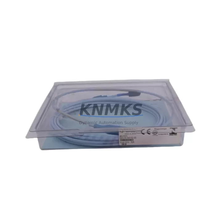
Overview
Bently Nevada 330130-045-02-05 Migration-Ready Extension Cable for Legacy Control Systems
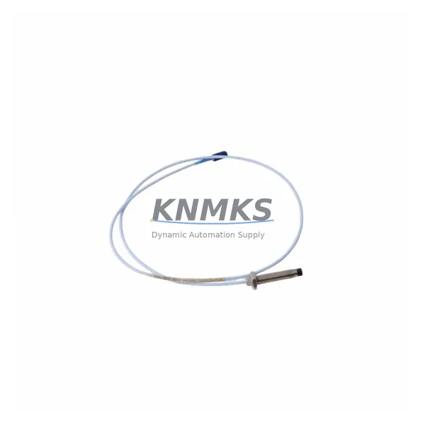
The Bently Nevada 330130-045-02-05 is a 5-metre (16.4 ft) proximity probe extension cable engineered for the 3300 XL and 3500 Series continuous vibration monitoring platforms. As legacy DCS and machinery protection systems approach end-of-life, this cable remains a critical link in the signal chain between the proximity probe and the proximitor/driver module. Whether you are executing a full control system migration, replacing a failed cable on a running train, or building a spare-parts inventory ahead of a planned shutdown, the 330130-045-02-05 provides a verified, drop-in replacement path with no firmware changes and no re-ranging of the proximitor required.
Engineers retrofitting older 3300 Series racks to the current 3500 Series architecture frequently encounter mismatches in cable length, connector type, and shield termination practice. The 330130-045-02-05 resolves these issues by maintaining the same 9-pin Bently Nevada connector standard and the same 50-ohm coaxial construction used across the 330130 family. Before installation, confirm that the total probe system length — probe body plus extension cable — matches the gap voltage calibration curve stored in the proximitor. For a standard 5 mm probe gap on a steel target, the combined system length must fall within the calibrated range of the paired 330180 or 330190 proximitor driver. If the existing proximitor is a legacy 3300/05 or 3300/16 module, verify that the driver’s input impedance specification is compatible before energising the loop.
Terminal wiring during a retrofit requires attention to shield grounding practice. The 330130-045-02-05 uses a single-point shield drain that must be grounded at the proximitor end only; grounding at both ends introduces a ground loop that degrades the signal-to-noise ratio and can trigger false high-vibration trips on the 3500/42M or 3500/45 monitor cards. When replacing cable in an existing installation, photograph the original shield termination before disconnecting, and replicate it exactly on the new cable.
Migration Compatibility Table
| Parameter | 330130-045-02-05 Specification | Retrofit / Migration Note |
|---|---|---|
| Cable Length | 5 m (16.4 ft) | Verify total probe system length matches proximitor calibration range |
| Connector Type | Bently Nevada 9-pin coaxial | Compatible with all 3300 XL and 3500 Series proximitor inputs |
| Impedance | 50 Ω coaxial | Match to 330180 / 330190 proximitor driver specification |
| Shield Termination | Single-point, proximitor end | Do not ground at probe end — prevents ground loop on 3500/42M, 3500/45 |
| Communication Protocol | Analogue eddy-current signal (no digital protocol) | No protocol migration required; signal passes transparently to monitor card |
| Installation Space | Standard conduit / cable tray routing | Confirm bend radius ≥ 50 mm to avoid signal attenuation |
| Firmware Compatibility | Not applicable (passive cable) | No firmware update required on 3500 rack after cable swap |
| Replacement Path | Direct drop-in for 330130-045-02-05 | No re-ranging of proximitor required if probe body is unchanged |
| Support terms | support terms confirmed by quotation | Covered from date of shipment; pre-shipment continuity and insulation test included |
Retrofit Planning for Existing Automation Systems
A successful cable retrofit begins well before the maintenance window opens. Start by pulling the loop drawing for the affected measurement point and confirming the probe model — typically a 330101, 330103, or 330105 proximity probe — alongside the proximitor part number. The 330130-045-02-05 is calibrated as a system with these probes; substituting a different probe body without recalibrating the proximitor will shift the gap voltage curve and introduce a measurement error that the 3500 rack will not flag as a fault.
In installations where the 3500 rack communicates over Modbus RTU or Ethernet/IP to a DCS historian, the cable swap itself does not affect the communication link. However, if the rack is also connected to a System 1 condition monitoring platform via the 3500/92 communication gateway, confirm that the channel configuration in System 1 still maps correctly to the physical slot after any rack re-addressing that may accompany the retrofit. Re-addressing a 3500 rack module requires the Rack Configuration Software and a programming cable such as the 129769-01 serial interface cable.
For installations that include a 3500/20 power supply module or a redundant 3500/20-01 power supply pair, verify that the total current draw of the rack does not increase after adding replacement modules during the same outage window. The 3500/20 is rated at 40 W; adding a new 3500/42M vibration monitor card alongside the cable replacement can push the rack close to its power budget if the existing supply is already loaded. A 3500/15 power supply interface module may be required if the rack is being expanded at the same time.
I/O wiring at the junction box between the probe and the extension cable should be inspected for corrosion, moisture ingress, and mechanical damage before the new 330130-045-02-05 is terminated. Replace the junction box O-ring seal if the installation is in a classified area or exposed to washdown. After termination, perform a static gap check with a digital voltmeter before closing the junction box: at the nominal 1.0 mm gap, the DC output of the proximitor should read approximately −7.87 V for a standard 3300 XL system. Record this value in the maintenance log as the baseline for future trend comparison.
Downtime Control During System Migration
Minimising unplanned downtime during a cable replacement on a running machine train requires a structured bypass and restore sequence. Where the 3500 rack supports channel bypass, activate the bypass on the affected measurement point before disconnecting the old cable. This prevents a spurious high-vibration trip from reaching the turbine control system or the emergency shutdown logic while the loop is open. Document the bypass activation time in the permit-to-work system and set a hard time limit aligned with your site’s safety instrumented system bypass policy.
If the machine cannot be bypassed — for example, on a single-string compressor with no standby — consider a hot-swap approach using a temporary extension cable routed outside the conduit while the permanent cable is replaced. This keeps the measurement loop live throughout the work and eliminates the trip risk entirely. Confirm with the OEM or your machinery protection engineer that the temporary routing does not introduce electromagnetic interference from adjacent power cables before proceeding.
After the new 330130-045-02-05 is installed and the junction box is closed, restore the channel from bypass and observe the gap voltage and vibration trend for a minimum of 15 minutes before releasing the permit. Compare the live gap voltage against the pre-outage baseline. A deviation of more than ±0.5 V indicates a wiring error, a probe position change, or a proximitor fault that must be resolved before the bypass is removed. All field calibration data, as-found and as-left gap voltages, and the cable serial number should be recorded in the plant CMMS against the equipment tag.
Retrofit Support FAQ
Q1: Is the 330130-045-02-05 a direct replacement for the older 330130-045-01-00 cable?
A: Yes. The -02-05 revision maintains the same electrical specification and connector standard as the -01-00 revision. No re-calibration of the proximitor is required when substituting one for the other, provided the probe body and gap setting remain unchanged.
Q2: What pre-shipment testing is performed on this cable?
A: Each 330130-045-02-05 is tested for DC continuity, centre-conductor-to-shield insulation resistance (minimum 100 MΩ at 500 V DC), and connector integrity before shipment. A test record is available on request.
Q3: Can this cable be used with a non-Bently Nevada proximitor from a third-party vibration monitoring system?
A: The cable is a passive coaxial assembly and is electrically compatible with any proximitor that accepts a 50-ohm input. However, the gap voltage calibration curve is optimised for Bently Nevada 330180 and 330190 Series proximitors. Using the cable with a third-party driver requires independent system calibration and is outside the scope of the support terms confirmed by quotation.
Q4: What is the lead time and support terms coverage?
A: Stock units ship within 1–3 business days. The 330130-045-02-05 carries a support terms confirmed by quotation from the date of shipment, covering manufacturing defects in materials and workmanship. Support requests are processed through admin@knmks.com.
© 2026 KNMKS. All rights reserved.
Original Source: https://knmks.com
Contact: admin@knmks.com | +86 18359268345
Product Identification
- Brand / Ecosystem
-
Bently Nevada
Bently Nevada - Model / Series
-
330130-045-02-05
Bently Nevada 3300 XL / 3301 Series - Product Family
- Cables & Connectors
- Availability Status
- Available on request after model and quantity confirmation
- Inquiry Type
- B2B RFQ, replacement inquiry and project spare-part request
- Pre-Quote Check
- Exact SKU, brand, series, quantity, nameplate photos and destination country are checked before quotation
System Path
Where this product fits in the KNMKS automation structure.
Specification & Inquiry Focus
- Cable range
- Sensor, servo, network and circular connectors
- Common needs
- Length, pin count, shielding and plug type
- Project support
- Machine wiring and installation kits
Buyer Confirmation
Information KNMKS checks before replying.
- Exact model
- 330130-045-02-05
- Brand / ecosystem
- Bently Nevada
- Product family
- Cables & Connectors
- Application note
- Replacement, maintenance, project build or spare-part list
- Useful photos
- Nameplate, installed unit, cabinet layout or connector side
- Delivery details
- Quantity, destination country and target schedule
Document Support
Files and notes can be confirmed during quotation.
- Product photos or nameplate confirmation when available
- Packing and delivery notes before quotation confirmation
- Support scope and delivery terms confirmed per inquiry
- Export document coordination for qualified B2B requests
Inquiry Support
- Cable length and connector type confirmation
- Servo, sensor and network cable inquiry
- Accessory kits for installation teams
What to Send Us
- Brand and exact model number: Bently Nevada 330130-045-02-05
- Quantity and required delivery time
- Application, replacement requirement or nameplate photo
- Destination country and shipping preference
RFQ Preparation
This is a product inquiry page built for RFQ communication.
Fast Model Check
Send this model to KNMKS for confirmation.
Include quantity, destination country and photos if this is a maintenance replacement. The inquiry will be saved with a reference number after submission.
Brand & Compatibility Note
KNMKS displays automation product information for well-known industrial brand ecosystems and compatible replacement references. Brand names are used for product identification and compatibility reference only; final availability and commercial terms are confirmed per quotation.
 Manufacturing
 Machine Tools
 Packaging
 Energy & Power
 PLCs & Controllers
 HMI & Displays
 Servo Systems
 Variable Frequency Drives