
Overview
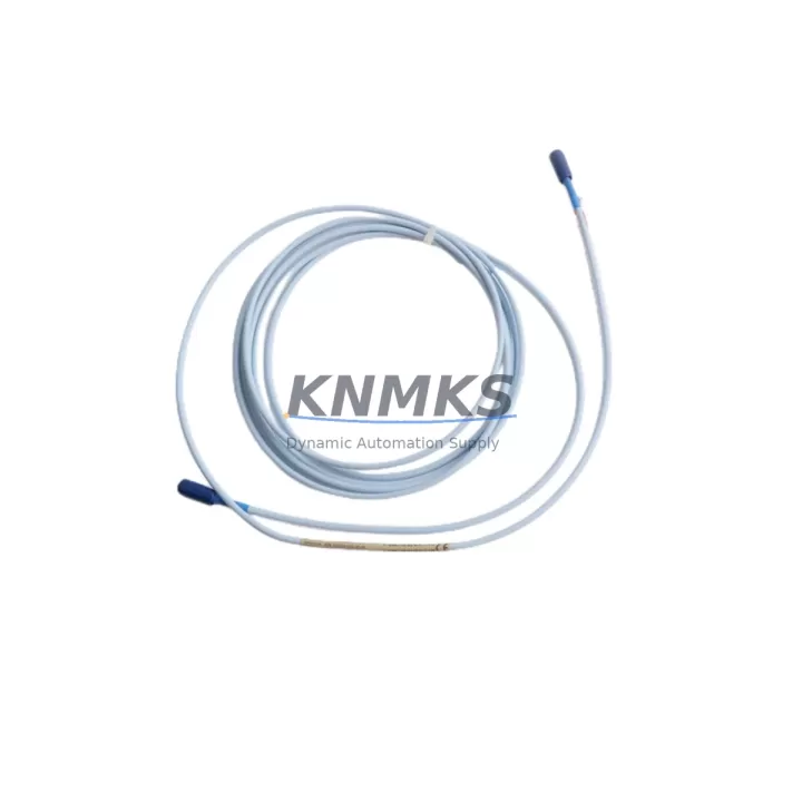
Bently Nevada 330130-035-00-00 Migration-Ready Proximity Transducer: Legacy System Retrofit & Upgrade
The Bently Nevada 330130-035-00-00 is an 8mm eddy-current proximity transducer engineered for the 3300 XL Proximity System platform. As aging turbomachinery protection systems reach end-of-service life, this transducer serves as a verified drop-in replacement for discontinued probes across rotating equipment installations in power generation, oil & gas, petrochemical, and heavy industrial environments. Whether you are executing a planned outage upgrade, responding to a failed sensor, or extending the operational life of a legacy monitoring rack, the 330130-035-00-00 delivers the dimensional accuracy, signal integrity, and system compatibility required for a low-risk retrofit.
Facilities operating original Bently Nevada 3300 XL monitor racks — including the 3300/16, 3300/20, and 3300/25 monitor cards — will find this transducer fully compatible with existing field wiring, extension cable assemblies, and proximitor driver electronics. The probe tip geometry, thread specification (M10 × 1.0), and output sensitivity (200 mV/mil, −18 VDC nominal) match the original factory specification, eliminating the need for recalibration of the monitor card or modification of the Keyphasor® reference channel configuration.
Migration Compatibility Table
| Parameter | Detail |
|---|---|
| SKU / Part Number | 330130-035-00-00 |
| Brand / Series | Bently Nevada / 3300 XL Proximity System |
| Probe Diameter | 8mm eddy-current tip |
| Cable Length | 35 cm integral cable (extension cable ordered separately) |
| Thread Specification | M10 × 1.0 |
| Output Sensitivity | 200 mV/mil (7.87 V/mm) |
| Nominal Bias Voltage | −18 VDC |
| Compatible Monitor Cards | 3300/16, 3300/20, 3300/25, 3500/40M, 3500/42M |
| Compatible Proximitor Drivers | 330180 series, 330100 series |
| Installation Clearance | Confirm minimum 25mm radial clearance from shaft surface |
| Replacement for Discontinued Models | 330130-035-00-00 (original), 330130-035-01-00, 330130-035-02-00 |
| Communication / Signal Type | Analog DC voltage (no fieldbus protocol required) |
| Retrofit Risk Level | Low — direct dimensional and electrical replacement |
| Commissioning Requirement | Gap voltage verification at −10 to −18 VDC; no monitor card reconfiguration required |
| Support terms | 12 months from date of shipment |
| Origin | USA |
Retrofit Planning for Existing Automation Systems
A successful proximity transducer retrofit begins well before the maintenance window opens. Engineers replacing the 330130-035-00-00 in an active turbomachinery protection loop must account for several interdependent system elements. The 330180-91-00 proximitor (or equivalent driver module) mounted in the field junction box must be confirmed compatible with the replacement probe’s tip geometry and cable impedance. Mismatched proximitor-probe combinations produce gap voltage errors that can trigger nuisance trips or, worse, mask genuine shaft displacement events.
Extension cable assemblies — typically from the 330130 or 330140 series — must be inspected for insulation degradation, connector corrosion, and shield continuity before reuse. A corroded BNC connector or a cracked cable jacket introduces noise into the −18 VDC signal path that no monitor card filtering can fully compensate. Where cable replacement is warranted, confirm that the total system cable length (probe integral cable + extension) remains within the proximitor’s specified range to maintain calibrated sensitivity.
At the monitor rack level, verify that the 3300/16 or 3300/20 monitor card’s gap setpoints, alert thresholds, and danger thresholds are documented before disconnecting the old probe. Many legacy installations carry undocumented field adjustments made during original commissioning. Photograph or record all potentiometer positions and DIP switch configurations before any hardware is disturbed. If the facility has migrated vibration data to a System 1 condition monitoring platform, confirm that the channel tag mapping and engineering unit scaling remain consistent after the probe swap.
For installations where the 3300 XL rack itself is being retired in favor of a 3500 Series rack migration, the 330130-035-00-00 probe remains compatible with 3500/40M and 3500/42M monitor modules, provided the proximitor driver is updated accordingly. This cross-generation compatibility significantly reduces field sensor replacement costs during a full rack upgrade, as the existing probe and extension cable infrastructure can often be retained. The 3500/22M transient data interface module should also be configured to accept the analog channel inputs from the retained 330130 probes during the transition period.
Where I/O expansion is part of the modernization scope — for example, adding axial position monitoring channels alongside existing radial vibration channels — plan the rack slot allocation and power supply loading before the outage. The 3500/15 power supply module’s current budget must accommodate all active monitor cards, I/O modules, and communication gateway cards simultaneously. Undersized power supply loading is a common commissioning failure mode in expanded 3500 racks that is easily avoided with pre-outage load calculations.
Downtime Control During System Migration
Minimizing unplanned downtime during a proximity transducer replacement requires a structured pre-outage preparation protocol. Before the maintenance window, bench-test the replacement 330130-035-00-00 against a known-good proximitor driver to confirm gap voltage output within specification (typically −10.0 to −18.0 VDC across the linear range). Document the as-found gap voltage on the installed probe before removal — this establishes the baseline for the as-left verification on the new probe and confirms that the target gap distance (typically 2.0 mm for 8mm probes) is achievable within the existing bracket geometry.
Preserve the original program logic and alarm configuration in the monitor system throughout the swap. For facilities using System 1 Evolution software, export the channel configuration file before the outage so that any accidental parameter loss during rack power cycling can be restored within minutes rather than hours. If the monitor rack must be de-energized, coordinate with the control room to place the associated machinery protection channels in bypass mode through the DCS or safety instrumented system — never leave a running machine unprotected during a monitor card power interruption.
After installation, perform a systematic gap voltage sweep by adjusting the probe standoff distance in 0.25 mm increments while recording the proximitor output voltage. Plot the resulting calibration curve and confirm that the linear range center point falls within ±0.5 VDC of the original as-found value. This verification step, which typically requires less than 20 minutes per channel, is the single most effective measure for confirming correct installation before returning the machine to service. All calibration records should be retained in the facility’s maintenance management system for future reference and regulatory compliance.
Retrofit Support FAQ
Q1: Is the 330130-035-00-00 a direct replacement for older 330130 series probes with different suffix codes?
In most cases, yes. The −035 designation indicates a 35 cm integral cable length. Probes with suffix variations such as −01-00 or −02-00 typically reflect minor manufacturing revisions that do not affect dimensional or electrical compatibility. However, always verify the thread specification (M10 × 1.0) and tip diameter (8mm) against the installed bracket before ordering. If the original probe carried a non-standard sensitivity specification (e.g., 100 mV/mil for special-order configurations), confirm the replacement sensitivity matches before installation.
Q2: What commissioning checks are required after installing the replacement probe?
The minimum commissioning checklist includes: (1) gap voltage verification at the target standoff distance, (2) confirmation that the proximitor output falls within the monitor card’s configured input range, (3) a slow-roll vibration check to confirm the signal is noise-free at low shaft speeds, and (4) a review of the monitor card’s OK relay status to confirm the channel is not in fault condition. For API 670-compliant installations, a full calibration record must be completed and signed off by the responsible engineer before the machine is returned to service.
Q3: Do you provide pre-shipment testing, and what does the support terms confirmed by quotation cover?
Yes. Every 330130-035-00-00 unit is functionally tested against a calibrated proximitor driver before shipment. The support terms confirmed by quotation cover manufacturing defects, out-of-specification sensitivity, and connector integrity. It does not cover damage resulting from incorrect installation gap, reverse polarity wiring, or mechanical impact. Support requests are processed with return authorization; replacement units are dispatched within 5 business days of claim approval.
Q4: Is stock available for immediate shipment, and can you supply multiple units for a fleet replacement program?
Stock is maintained for the 330130-035-00-00 to support both emergency single-unit replacements and planned fleet maintenance programs. For orders of 5 units or more, contact our sales team to confirm lead time, batch test documentation availability, and volume pricing. We can also advise on compatible extension cables, proximitor drivers, and mounting hardware to support a complete retrofit kit for your specific machine type.
© 2026 KNMKS. All rights reserved.
Original Source: https://knmks.com
Contact: admin@knmks.com | +86 18359268345
Product Identification
- Brand / Ecosystem
-
Bently Nevada
Bently Nevada - Model / Series
-
330130-035-00-00
Bently Nevada 3300 XL / 3301 Series - Product Family
- Sensors
- Availability Status
- Available on request after model and quantity confirmation
- Inquiry Type
- B2B RFQ, replacement inquiry and project spare-part request
- Pre-Quote Check
- Exact SKU, brand, series, quantity, nameplate photos and destination country are checked before quotation
System Path
Where this product fits in the KNMKS automation structure.
Specification & Inquiry Focus
- Sensor range
- Photoelectric, proximity and process sensors
- Common needs
- Output type, distance and connector
- Project support
- Machine detection and replacement inquiry
Buyer Confirmation
Information KNMKS checks before replying.
- Exact model
- 330130-035-00-00
- Brand / ecosystem
- Bently Nevada
- Product family
- Sensors
- Application note
- Replacement, maintenance, project build or spare-part list
- Useful photos
- Nameplate, installed unit, cabinet layout or connector side
- Delivery details
- Quantity, destination country and target schedule
Document Support
Files and notes can be confirmed during quotation.
- Product photos or nameplate confirmation when available
- Packing and delivery notes before quotation confirmation
- Support scope and delivery terms confirmed per inquiry
- Export document coordination for qualified B2B requests
Inquiry Support
- NPN/PNP, analog and digital output checking
- Connector and cable compatibility review
- Fast inquiry support for maintenance teams
What to Send Us
- Brand and exact model number: Bently Nevada 330130-035-00-00
- Quantity and required delivery time
- Application, replacement requirement or nameplate photo
- Destination country and shipping preference
RFQ Preparation
This is a product inquiry page built for RFQ communication.
Fast Model Check
Send this model to KNMKS for confirmation.
Include quantity, destination country and photos if this is a maintenance replacement. The inquiry will be saved with a reference number after submission.
Brand & Compatibility Note
KNMKS displays automation product information for well-known industrial brand ecosystems and compatible replacement references. Brand names are used for product identification and compatibility reference only; final availability and commercial terms are confirmed per quotation.
 Manufacturing
 Machine Tools
 Packaging
 Energy & Power



 PLCs & Controllers
 HMI & Displays
 Servo Systems
 Variable Frequency Drives