
Overview
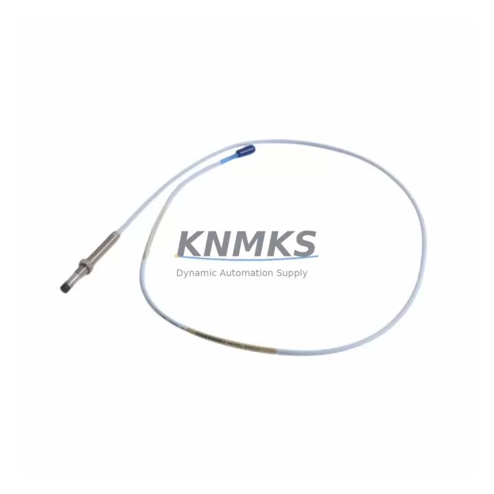
Bently Nevada 330105-02-12-15-02-05 Migration-Ready Proximity Transducer for Legacy Control Systems
The Bently Nevada 330105-02-12-15-02-05 is an 8mm proximity transducer designed for the 3300 XL series vibration monitoring platform. As aging machinery protection systems approach end-of-life and original spare parts become increasingly scarce, this unit serves as a direct migration-ready replacement for facilities operating legacy Bently Nevada 3300 and 3500 series monitoring architectures. Whether you are managing a planned retrofit, responding to an unplanned failure, or building out a long-term spare parts strategy, the 330105-02-12-15-02-05 provides a verified drop-in solution that minimizes engineering rework and reduces commissioning time on the plant floor.
This transducer is part of the 3300 XL proximity system, which uses a three-component measurement chain: the transducer itself, an extension cable (such as the 330130 series), and a proximitor/oscillator (such as the 3300 XL 8mm proximitor). When planning a retrofit, all three components must be evaluated together to ensure the overall system gain and output voltage range remain within the monitor’s acceptance window. Substituting only the transducer without verifying the extension cable length and proximitor model can introduce calibration offsets that trigger false alerts or mask real machinery faults.
Migration Compatibility Table
| Parameter | Details |
|---|---|
| SKU / Part Number | 330105-02-12-15-02-05 |
| Brand / Series | Bently Nevada / 3300 XL 8mm Proximity System |
| Probe Tip Diameter | 8mm |
| Cable Length | 2m integral cable (verify against extension cable for total system length) |
| Thread Size | M10 x 1.0 (confirm mounting boss thread before installation) |
| Compatible Proximitor | 3300 XL 8mm Proximitor (e.g., 330180 series) |
| Compatible Extension Cable | 330130 series (5m, 9m options — match to total system length requirement) |
| Compatible Monitors | 3300 series, 3500 series (verify channel card input range) |
| Output Sensitivity | 200 mV/mil (7.87 V/mm) — confirm monitor channel card calibration |
| Installation Space | Standard 8mm probe boss; confirm radial clearance and axial access |
| Wiring / Terminal Compatibility | Coaxial connector; verify junction box and terminal block compatibility |
| Communication / Protocol | Analog voltage output; no fieldbus protocol — monitor handles signal processing |
| Retrofit Recommendation | Direct replacement for discontinued 330105 variants; verify full system chain |
| Commissioning Focus | Gap voltage verification, sensitivity check, alert/danger setpoint confirmation |
| Support terms | 12 Months |
Retrofit Planning for Existing Automation Systems
Successful integration of the 330105-02-12-15-02-05 into an existing machinery protection system begins well before the transducer arrives on site. The first step is a full audit of the existing measurement chain. Technicians should document the current proximitor model — typically a 330180 series 8mm proximitor — and confirm that the new transducer’s integral cable length, combined with the existing 330130 extension cable, matches the total system length for which the proximitor is calibrated. Mismatched system lengths are one of the most common sources of commissioning errors during proximity transducer replacements and can result in incorrect gap voltage readings that fall outside the linear range.
Terminal wiring at the junction box must also be inspected. The coaxial cable shield grounding practice, connector torque specification, and any intermediate terminal blocks between the probe and the proximitor enclosure should be documented and preserved during the swap. If the existing junction box uses older-style terminal strips that are corroded or mechanically worn, this is an appropriate time to replace them as part of the broader retrofit scope.
On the monitor side, if the facility is running a 3500 series rack — for example, a 3500/42M Proximitor/Seismic Monitor — the channel card configuration should be reviewed to confirm that the input sensitivity, full-scale range, and transducer type selection match the 330105-02-12-15-02-05 specifications. If the rack also includes a 3500/20 Rack Interface Module for Modbus or other communication output, the channel mapping and tag assignments should be verified against the existing DCS or SCADA configuration before the transducer is swapped, to avoid alarm floods or lost data points during the transition window.
For facilities that are simultaneously upgrading from a 3300 series rack to a 3500 series rack as part of a broader control system modernization, the transducer itself is typically reusable across both platforms, which significantly reduces the hardware cost of the rack migration. In these cases, the primary engineering effort shifts to reconfiguring the 3500 rack’s I/O module assignments, updating the System 1 or System 1 Evolution condition monitoring software database, and re-establishing communication links to the plant historian or DCS. The 330105-02-12-15-02-05 can remain in place on the machine while the rack and software infrastructure is upgraded around it, which is a practical approach to minimizing machine downtime during phased modernization projects.
Where facilities are also replacing nearby instrumentation — such as velocity seismic transducers on the same machine train — it is worth coordinating the proximity transducer replacement with any planned work on the 3500/25 Enhanced Keyphasor Module or associated Keyphasor transducers, since phase reference data is critical for vector-based vibration analysis and should not be interrupted during a partial retrofit.
Downtime Control During System Migration
Minimizing unplanned downtime during a proximity transducer replacement requires a structured pre-outage preparation process. Before the machine is taken offline, the existing gap voltage should be recorded at the monitor display or via the System 1 software interface. This baseline reading, combined with the physical gap measurement at the probe tip, provides the reference point for post-installation verification. If the gap voltage is outside the normal operating window prior to removal, this should be documented and investigated — it may indicate a worn probe tip, a damaged extension cable, or a failing proximitor rather than a transducer failure.
During the physical swap, the original program logic in the associated safety or control system should not be modified. If the proximity channel feeds a trip relay through a 3500 series I/O module or a legacy relay output card, the trip circuit should be defeated through the monitor’s inhibit function rather than by modifying PLC or DCS logic. This preserves the original control program integrity and eliminates the risk of introducing logic errors during what should be a hardware-only maintenance event.
After installation, the new transducer should be gapped to the manufacturer’s recommended voltage — typically between -10 VDC and -18 VDC for 8mm systems, with the optimal gap voltage near -12 VDC — before the inhibit is released and the monitor is returned to normal operation. A post-installation functional test, including a simulated vibration check if a calibration shaker is available, confirms that the full measurement chain is operating correctly before the machine is restarted. All findings should be recorded in the site’s maintenance management system to support future spare parts planning and support terms tracking.
For facilities managing multiple machines with similar transducer configurations, a staged replacement approach — replacing one machine at a time while maintaining production on others — is the most effective strategy for controlling total downtime exposure across a planned outage window.
Retrofit Support FAQ
Q: Is the 330105-02-12-15-02-05 a direct replacement for my existing 330105 series transducer?
A: In most cases, yes. The 330105-02-12-15-02-05 is a current-production unit within the 3300 XL 8mm proximity system family. However, you should verify the integral cable length, thread specification, and total system length against your existing proximitor calibration before installation. If your site uses a non-standard system length, a different 330105 variant or a custom extension cable may be required.
Q: What commissioning steps are required after installation?
A: After physical installation, set the probe gap to achieve the target gap voltage (typically -12 VDC ± 1 VDC for 8mm systems). Verify the output voltage at the monitor input terminals, confirm that alert and danger setpoints are active, and release any inhibits applied during the swap. Document the as-left gap voltage and compare it to the pre-removal baseline. If the readings differ significantly, inspect the extension cable and proximitor before returning the machine to service.
Q: Can I use this transducer with a 3500 series monitor rack?
A: Yes. The 330105-02-12-15-02-05 is compatible with 3500 series monitor racks, including the 3500/42M Proximitor/Seismic Monitor, provided the channel card is configured for 8mm transducer input and the total system length matches the proximitor calibration. Confirm the channel configuration in the 3500 Rack Configuration Software before installation.
Q: What support terms and supply terms apply?
A: All units supplied by KNMKS carry a support terms confirmed by quotation covering manufacturing defects under normal operating conditions. Stock is maintained for prompt shipment, and each unit undergoes pre-shipment functional testing before dispatch. Contact our sales team to confirm current lead times and available inventory for your project schedule.
© 2026 KNMKS. All rights reserved.
Original Source: https://knmks.com
Contact: admin@knmks.com | +86 18359268345
Product Identification
- Brand / Ecosystem
-
Bently Nevada
Bently Nevada - Model / Series
-
330105-02-12-15-02-05
Bently Nevada 3300 XL / 3301 Series - Product Family
- Sensors
- Availability Status
- Available on request after model and quantity confirmation
- Inquiry Type
- B2B RFQ, replacement inquiry and project spare-part request
- Pre-Quote Check
- Exact SKU, brand, series, quantity, nameplate photos and destination country are checked before quotation
System Path
Where this product fits in the KNMKS automation structure.
Specification & Inquiry Focus
- Sensor range
- Photoelectric, proximity and process sensors
- Common needs
- Output type, distance and connector
- Project support
- Machine detection and replacement inquiry
Buyer Confirmation
Information KNMKS checks before replying.
- Exact model
- 330105-02-12-15-02-05
- Brand / ecosystem
- Bently Nevada
- Product family
- Sensors
- Application note
- Replacement, maintenance, project build or spare-part list
- Useful photos
- Nameplate, installed unit, cabinet layout or connector side
- Delivery details
- Quantity, destination country and target schedule
Document Support
Files and notes can be confirmed during quotation.
- Product photos or nameplate confirmation when available
- Packing and delivery notes before quotation confirmation
- Support scope and delivery terms confirmed per inquiry
- Export document coordination for qualified B2B requests
Inquiry Support
- NPN/PNP, analog and digital output checking
- Connector and cable compatibility review
- Fast inquiry support for maintenance teams
What to Send Us
- Brand and exact model number: Bently Nevada 330105-02-12-15-02-05
- Quantity and required delivery time
- Application, replacement requirement or nameplate photo
- Destination country and shipping preference
RFQ Preparation
This is a product inquiry page built for RFQ communication.
Fast Model Check
Send this model to KNMKS for confirmation.
Include quantity, destination country and photos if this is a maintenance replacement. The inquiry will be saved with a reference number after submission.
Brand & Compatibility Note
KNMKS displays automation product information for well-known industrial brand ecosystems and compatible replacement references. Brand names are used for product identification and compatibility reference only; final availability and commercial terms are confirmed per quotation.
 Manufacturing
 Machine Tools
 Packaging
 Energy & Power



 PLCs & Controllers
 HMI & Displays
 Servo Systems
 Variable Frequency Drives