
Overview
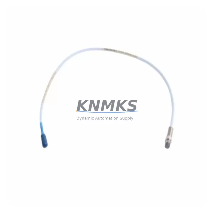
Bently Nevada 330105-02-12-05-02-CN Retrofit Probe for 3300 XL Legacy Systems
The Bently Nevada 330105-02-12-05-02-CN is a migration-ready proximity probe engineered for direct replacement and retrofit integration within Bently Nevada 3300 XL continuous vibration monitoring systems. Designed to meet the demands of legacy control system modernization, this probe supports drop-in installation without requiring changes to existing field wiring, conduit routing, or monitor rack configurations. It is an essential spare part for facilities managing aging turbomachinery protection infrastructure where original OEM supply has been discontinued or lead times are unacceptable.
The 330105-02-12-05-02-CN operates as part of the 3300 XL eddy-current proximity sensing chain, working in conjunction with the 330130 extension cable and the 3300 XL proximitor/seismic transducer module. When planning a retrofit or replacement, engineers must confirm the total system length — probe cable, extension cable, and proximitor — to ensure the combined assembly remains within the calibrated gap voltage range. Incorrect system length will result in calibration offset and false trip conditions on the 3500/42M or 3500/40M monitor modules downstream.
For facilities operating Bently Nevada 3500 series rack systems, the 330105-02-12-05-02-CN integrates directly with existing 3500 rack backplane wiring without modification. The probe’s 5-metre integral cable and standard TNC connector interface are compatible with the 330130-080-00-00 extension cable commonly installed in turbine pedestals and compressor trains. Before installation, verify that the proximitor supply voltage (typically –24 VDC from the 3500/15 power supply module) is within specification and that the barrier or isolator in the junction box is rated for the probe’s output impedance.
Migration Compatibility Table
| Parameter | 330105-02-12-05-02-CN | Retrofit Notes |
|---|---|---|
| Probe Series | 3300 XL 8mm | Compatible with all 3300 XL proximitor/seismic modules |
| System Length | 5m probe + extension cable | Confirm total system length matches proximitor calibration |
| Connector Type | TNC (integral cable) | Mates with 330130 series extension cables |
| Target Material | Steel / Inconel | Verify shaft material; re-calibrate if non-standard alloy |
| Supply Voltage | –24 VDC nominal | Confirm 3500/15 power supply output before installation |
| Monitor Compatibility | 3500/40M, 3500/42M, 3300 XL monitors | No firmware update required for standard replacement |
| Installation Space | 8mm probe tip, standard bracket mount | Confirm bracket clearance and probe holder thread (M10) |
| Communication Link | Analogue (gap voltage output) | No protocol migration required; analogue signal chain preserved |
| Replacement Recommendation | Direct drop-in for 330105-02-12-05-02-CN | No re-wiring required if extension cable is undamaged |
| Commissioning Focus | Gap voltage, sensitivity, OK relay | Set gap to –10.0 VDC ±0.2 VDC at mid-gap; verify OK output |
| Support terms | 12 Months | Covers manufacturing defects; pre-shipment tested |
Retrofit Planning for Existing Automation Systems
Successful retrofit of the 330105-02-12-05-02-CN into an operating plant requires a structured pre-outage engineering review. Begin by auditing the existing probe holder, bracket, and conduit entry to confirm the 8mm probe body and M10 thread are compatible with the installed hardware. In many legacy installations, the probe holder may have been custom-machined; measure the bore diameter and thread pitch before ordering replacement hardware.
The extension cable — typically a 330130-080-00-00 or equivalent 8-metre assembly — should be inspected for jacket damage, connector corrosion, and continuity. A damaged extension cable will introduce noise into the gap voltage signal and cause nuisance trips on the 3500/42M dual-channel monitor. If the extension cable is being replaced simultaneously, ensure the new assembly is from the same calibrated system length family as the probe to maintain the –10.0 VDC mid-gap calibration point.
At the rack level, confirm that the 3500/15 power supply module is delivering stable –24 VDC to the I/O module terminal block. Voltage sag under load — particularly in older racks where the 3500/15 has not been replaced — can cause the proximitor output to drift outside the OK band, triggering a channel fault on the 3500/40M or 3500/42M. If the power supply is marginal, schedule its replacement alongside the probe to avoid a repeat outage.
For facilities migrating from older 3300 series monitors to the 3500 platform, the 330105-02-12-05-02-CN is fully compatible with both generations. The 3500 rack’s I/O module accepts the same terminal wiring as the legacy 3300 monitor, so field wiring from the junction box to the rack can be reused without modification. Update the 3500 rack configuration in System 1 or Rack Configuration Software to reflect the new channel assignment and alert/danger setpoints before energising the channel.
Where the control system includes a DCS or safety PLC receiving 4–20 mA or relay outputs from the 3500 rack, verify that the output module configuration — particularly the 3500/20 or 3500/22M communication gateway — is correctly mapped to the new channel. If the plant uses a Modbus RTU or FOUNDATION Fieldbus link between the 3500 rack and the DCS, no changes to the communication protocol are required; only the channel tag and engineering unit scaling may need updating in the DCS historian.
Signal isolators installed between the proximitor output and the DCS analogue input card should be checked for input range compatibility. Some legacy isolators are configured for a –24 VDC to 0 VDC input range; confirm the isolator’s input specification matches the probe’s gap voltage output range before commissioning.
Downtime Control During System Migration
Minimising unplanned downtime during proximity probe replacement requires pre-staging all replacement components — probe, extension cable, and any bracket hardware — before the maintenance window opens. A pre-shipment functional test, performed on every unit before dispatch, confirms that the probe’s sensitivity and OK relay operate within specification, eliminating the risk of receiving a defective unit during a time-critical outage.
Where the machine cannot be taken offline for an extended period, consider a phased replacement strategy: replace the probe and extension cable during a scheduled short outage, then perform full gap setting and calibration verification during the next planned maintenance window. The 3500 rack’s bypass function allows individual channels to be placed in bypass mode during probe replacement, preventing a channel fault from triggering a machine trip while the probe is disconnected.
Before re-energising the channel, verify the gap voltage at the proximitor output terminal using a calibrated digital multimeter. The target gap voltage for the 330105-02-12-05-02-CN at mid-gap is –10.0 VDC ±0.2 VDC. Record the as-found and as-left gap voltages in the maintenance management system to establish a baseline for future condition monitoring. Confirm that the OK relay on the 3500/40M or 3500/42M monitor has reset and that the channel is displaying a valid vibration reading before releasing the machine to operations.
For facilities with a System 1 condition monitoring platform, update the probe tag configuration to reflect the replacement date and new serial number. This ensures that trend data continuity is maintained and that any future alarm analysis correctly references the replacement event as a baseline reset point.
Retrofit Support FAQ
Q: Is the 330105-02-12-05-02-CN a direct replacement for the original Bently Nevada part?
A: Yes. This unit is a verified drop-in replacement for the original 330105-02-12-05-02-CN proximity probe. No field wiring changes, bracket modifications, or monitor reconfiguration are required for standard replacement in 3300 XL and 3500 series systems.
Q: What commissioning steps are required after installation?
A: After mechanical installation, set the probe gap to achieve a proximitor output of –10.0 VDC ±0.2 VDC using a non-conductive gap-setting tool. Verify the OK relay has reset on the 3500/40M or 3500/42M monitor, confirm the vibration reading is within the expected baseline range, and record as-left gap voltage in the maintenance log.
Q: Can this probe be used with both 3300 XL and 3500 series monitor racks?
A: Yes. The 330105-02-12-05-02-CN is compatible with both the legacy 3300 XL monitor platform and the current 3500 series rack system. No firmware updates or hardware adapters are required. Confirm the extension cable system length matches the proximitor calibration for the target platform.
Q: What support terms and pre-shipment testing is provided?
A: Every unit is pre-shipment tested for sensitivity, gap voltage output, and OK relay function before dispatch. A support terms confirmed by quotation cover manufacturing defects from the date of shipment. In-stock units are available for immediate dispatch to support urgent maintenance and unplanned outage scenarios.
© 2026 KNMKS. All rights reserved.
Original Source: https://knmks.com
Contact: admin@knmks.com | +86 18359268345
Product Identification
- Brand / Ecosystem
-
Bently Nevada
Bently Nevada - Model / Series
-
330105-02-12-05-02-CN
Bently Nevada 3300 XL / 3301 Series - Product Family
- Sensors
- Availability Status
- Available on request after model and quantity confirmation
- Inquiry Type
- B2B RFQ, replacement inquiry and project spare-part request
- Pre-Quote Check
- Exact SKU, brand, series, quantity, nameplate photos and destination country are checked before quotation
System Path
Where this product fits in the KNMKS automation structure.
Specification & Inquiry Focus
- Sensor range
- Photoelectric, proximity and process sensors
- Common needs
- Output type, distance and connector
- Project support
- Machine detection and replacement inquiry
Buyer Confirmation
Information KNMKS checks before replying.
- Exact model
- 330105-02-12-05-02-CN
- Brand / ecosystem
- Bently Nevada
- Product family
- Sensors
- Application note
- Replacement, maintenance, project build or spare-part list
- Useful photos
- Nameplate, installed unit, cabinet layout or connector side
- Delivery details
- Quantity, destination country and target schedule
Document Support
Files and notes can be confirmed during quotation.
- Product photos or nameplate confirmation when available
- Packing and delivery notes before quotation confirmation
- Support scope and delivery terms confirmed per inquiry
- Export document coordination for qualified B2B requests
Inquiry Support
- NPN/PNP, analog and digital output checking
- Connector and cable compatibility review
- Fast inquiry support for maintenance teams
What to Send Us
- Brand and exact model number: Bently Nevada 330105-02-12-05-02-CN
- Quantity and required delivery time
- Application, replacement requirement or nameplate photo
- Destination country and shipping preference
RFQ Preparation
This is a product inquiry page built for RFQ communication.
Fast Model Check
Send this model to KNMKS for confirmation.
Include quantity, destination country and photos if this is a maintenance replacement. The inquiry will be saved with a reference number after submission.
Brand & Compatibility Note
KNMKS displays automation product information for well-known industrial brand ecosystems and compatible replacement references. Brand names are used for product identification and compatibility reference only; final availability and commercial terms are confirmed per quotation.
 Manufacturing
 Machine Tools
 Packaging
 Energy & Power



 PLCs & Controllers
 HMI & Displays
 Servo Systems
 Variable Frequency Drives