
Overview
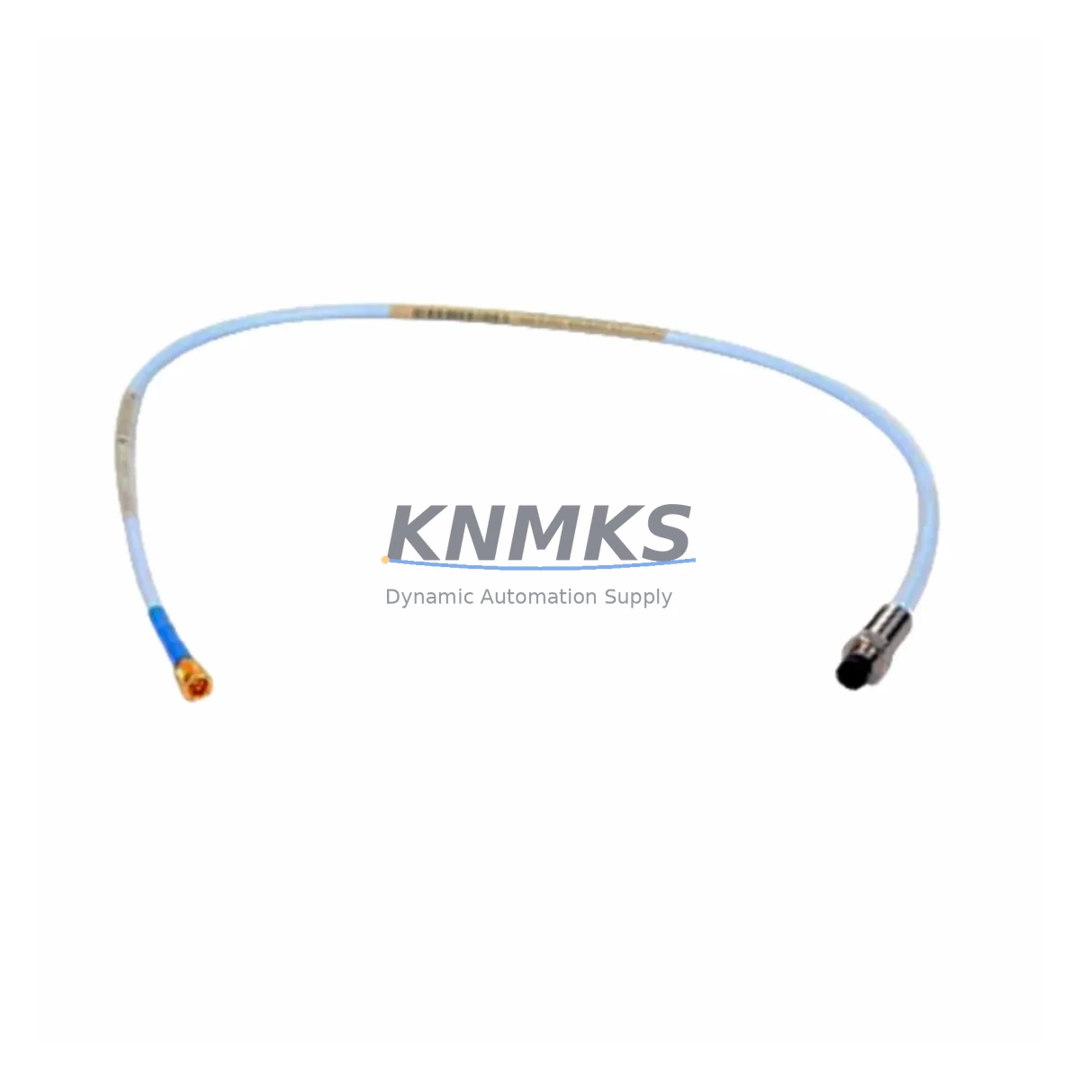
Bently Nevada 330105-02-12-05-02-05 Migration-Ready Proximity Transducer for Legacy Control Systems
The Bently Nevada 330105-02-12-05-02-05 is an 8mm proximity transducer engineered for drop-in replacement and retrofit integration within legacy 3300 XL continuous monitoring systems. As industrial facilities face increasing pressure to modernize aging vibration monitoring infrastructure, this transducer serves as a critical bridge between discontinued hardware generations and current-generation condition monitoring platforms. Whether you are replacing a failed sensor in a running plant, upgrading a control cabinet, or executing a full system migration from an obsolete 3300 Series rack to a modern 3500 Series monitoring system, the 330105-02-12-05-02-05 delivers verified electrical compatibility, dimensional interchangeability, and signal integrity that minimizes engineering risk during the transition.
Facilities operating rotating machinery — including steam turbines, compressors, pumps, and gearboxes — rely on proximity transducers to provide continuous shaft displacement and vibration data to protection and monitoring systems. When the original transducer reaches end-of-life or the OEM discontinues support, sourcing a verified replacement with traceable specifications becomes essential. The 330105-02-12-05-02-05 addresses this need directly: it maintains the standard 8mm tip diameter, 5-meter integral cable, and -24 VDC bias voltage output that the 3300 XL signal conditioning chain expects, ensuring that existing Proximitor sensor housings, extension cables, and junction boxes can be reused without modification.
Before installing this transducer as a replacement, engineers should confirm several key parameters. Power supply capacity at the local marshalling cabinet must support the transducer’s operating current draw, particularly when multiple channels are being replaced simultaneously. Terminal wiring at the field junction box should be inspected for correct polarity and shield grounding continuity, as improper grounding introduces noise that corrupts gap voltage readings. The Proximitor sensor — typically a 330180 Series or 330100 Series signal conditioner mounted in the rack — must be verified for firmware and hardware revision compatibility with the replacement transducer’s sensitivity specification of -7.87 V/mm. If the existing Proximitor is also at end-of-life, a coordinated replacement using a matched transducer-and-conditioner pair eliminates the risk of sensitivity mismatch between field and rack components.
For facilities migrating from the 3300 XL platform to the Bently Nevada 3500 Series, the 330105-02-12-05-02-05 can serve as an interim field device while rack-level hardware is upgraded in stages. The 3500/42M Proximitor I/O Module accepts the same -24 VDC transducer output, allowing the field wiring and transducer installation to remain unchanged while the rack, power supply module, and communication gateway are replaced. This phased approach is particularly valuable in continuous-process industries where full system shutdowns are costly and infrequent. During the migration window, the existing DCS or safety system I/O cards connected to the 3300 XL rack outputs should be mapped against the new 3500 Series output signal ranges to confirm that alarm setpoints and trip thresholds remain valid after the rack swap.
HMI screen configurations referencing the old channel addresses must be updated to reflect the new rack slot assignments in the 3500 Series. Communication links — whether using RS-232, RS-485 Modbus, or the System 1 Evolution software interface — require reconfiguration to recognize the new device node addresses. If the plant historian or condition monitoring software uses OPC DA or OPC UA tags mapped to the 3300 XL rack, those tag paths must be remapped before the new system goes live. Failure to update communication links before cutover is one of the most common causes of extended downtime during vibration monitoring system migrations.
Installation space confirmation is straightforward for this transducer: the 330105-02-12-05-02-05 uses the standard M10 x 1 thread mount and requires the same radial clearance as the original 3300 XL transducer it replaces. No bracket modification or probe holder machining is required in most standard installations. The 5-meter cable length accommodates the majority of field-to-junction-box routing distances encountered in turbine pedestals and compressor skids. Where cable routing requires extension, a compatible 330130 Series extension cable can be used to reach the Proximitor without signal degradation.
Every unit shipped by KNMKS undergoes pre-shipment functional testing that verifies gap voltage output, cable continuity, and connector integrity. Units are supplied with a test report confirming compliance with the original OEM specification. Stock is maintained to support urgent replacement requirements, with same-day dispatch available for in-stock items. All units are covered by a support terms confirmed by quotation against manufacturing defects, with technical support available throughout the confirmed support period to assist with installation, commissioning, and compatibility verification.
Migration Compatibility Table
| Parameter | 330105-02-12-05-02-05 (This Unit) | Legacy 3300 XL Requirement | 3500 Series Compatibility |
|---|---|---|---|
| Tip Diameter | 8 mm | 8 mm | Compatible |
| Thread Mount | M10 x 1 | M10 x 1 | Compatible |
| Cable Length | 5 m integral | 5 m standard | Compatible |
| Sensitivity | -7.87 V/mm | -7.87 V/mm | Verify Proximitor revision |
| Bias Voltage Output | -24 VDC nominal | -24 VDC | Compatible with 3500/42M |
| Power Supply | -24 VDC from Proximitor | 330180 / 330100 Series | 3500/42M I/O Module |
| Communication Protocol | Analog (passive transducer) | Analog signal chain | Compatible |
| Replacement Recommendation | Direct drop-in for 3300 XL; interim field device during 3500 Series migration | ||
| Commissioning Focus | Gap voltage verification, shield grounding, Proximitor sensitivity match | ||
| Support terms | 12 months from shipment date — manufacturing defects covered | ||
Retrofit Planning for Existing Automation Systems
A successful retrofit begins with a complete bill-of-materials audit of the existing monitoring rack. In a typical 3300 XL installation, the rack contains a power supply module, one or more Proximitor sensor modules such as the 330180-91-00 or 330100-90-01, and a series of transducer channels wired to field junction boxes. When planning a phased replacement, it is common to replace the transducer first, then the Proximitor conditioner, and finally the rack and power supply in a subsequent outage window. This sequence keeps the system operational between maintenance windows and limits the scope of each individual intervention.
Where the existing installation uses a 3300 XL rack with a dedicated rack power supply, the replacement power supply module must be sized to support all active transducer channels simultaneously. If the retrofit scope includes adding I/O channels — for example, expanding from four to eight vibration measurement points on a compressor train — the new rack power supply and backplane must be selected to accommodate the increased channel count. The 3500 Series backplane and associated I/O modules support modular expansion, making it straightforward to add axial position or speed measurement channels alongside the radial vibration channels served by the 330105-02-12-05-02-05 transducers.
Signal isolation requirements should be reviewed during retrofit planning. In installations where the transducer signal chain shares a common ground reference with other instrumentation, a signal isolator may be required to prevent ground loop interference from corrupting the gap voltage measurement. Terminal block wiring at the marshalling cabinet should be documented before any replacement work begins, as the original as-built drawings may not reflect field modifications made during previous maintenance cycles. Photographic documentation of the existing terminal assignments provides a reliable reference during reconnection after the new transducer is installed.
For facilities using a programming cable to configure or interrogate the 3500 Series rack after migration, the communication interface between the rack and the engineering workstation must be verified before the system is returned to service. The System 1 Evolution software requires correct COM port assignment and baud rate configuration to establish communication with the new rack. If the plant uses a DCS with hardwired 4–20 mA outputs from the monitoring rack, those output channels must be loop-checked after the rack replacement to confirm that the scaling and zero calibration remain correct.
Downtime Control During System Migration
Minimizing downtime during a vibration monitoring system migration requires careful pre-staging of replacement hardware, a clearly defined cutover sequence, and a tested rollback plan in case the new system does not achieve ready status within the planned maintenance window. For the 330105-02-12-05-02-05 transducer replacement specifically, the field installation can typically be completed within one to two hours per measurement point, provided that the probe holder thread condition is acceptable and the cable routing path is clear.
Before the maintenance window opens, the replacement transducer should be bench-tested against a known-good Proximitor to verify gap voltage output at the nominal installation gap. This pre-commissioning step confirms that the replacement unit is functional before it is installed in the field, eliminating the risk of discovering a defective unit after the original transducer has been removed. The original program logic in the protection system — including alarm setpoints, trip delays, and bypass configurations — should be exported and saved before any rack-level work begins, so that the configuration can be restored quickly if the migration encounters an unexpected issue.
During the cutover, the affected measurement channels should be placed in bypass mode in the protection system to prevent spurious trips while the transducer is disconnected and reconnected. Once the new transducer is installed and the gap is set to the correct nominal value — typically 1.0 to 1.5 mm for an 8mm probe — the channel should be brought out of bypass one at a time, with the gap voltage and vibration reading verified against the pre-migration baseline before the next channel is activated. This sequential verification approach ensures that any wiring error or sensitivity mismatch is identified and corrected before the full system is returned to automatic protection mode.
Field control continuity is maintained throughout the migration by keeping the DCS inputs active and monitoring the bypass status indicators on the HMI. Operators should be briefed on the expected duration of each bypass period and the criteria for returning each channel to active protection. Clear communication between the maintenance team and the control room is the single most effective measure for reducing the risk of an unplanned trip or missed alarm during the migration window.
Retrofit Support FAQ
Q: Is the 330105-02-12-05-02-05 a direct replacement for all 8mm 3300 XL proximity transducers?
A: It is a direct replacement for 3300 XL installations using 8mm transducers with M10 x 1 thread mounts, 5-meter integral cables, and -7.87 V/mm sensitivity. Installations using different cable lengths or sensitivity specifications require verification before ordering. Contact admin@knmks.com with your existing transducer part number for a compatibility confirmation.
Q: What commissioning steps are required after installing the replacement transducer?
A: After installation, set the probe gap to the nominal value specified in the machine manufacturer’s documentation (typically 1.0–1.5 mm for an 8mm probe). Verify the gap voltage output at the Proximitor terminal strip, confirm that the vibration reading is within the expected baseline range, and remove the channel bypass in the protection system. Document the as-found and as-left gap voltage values in the maintenance record.
Q: Does KNMKS perform pre-shipment testing on this transducer?
A: Yes. Every 330105-02-12-05-02-05 unit is functionally tested before shipment to verify gap voltage output, cable continuity, and connector integrity. A test report is included with each shipment. Units are covered by a support terms confirmed by quotation against manufacturing defects from the date of shipment.
Q: What is the typical lead time and stock availability?
A: KNMKS maintains inventory of the 330105-02-12-05-02-05 to support urgent replacement requirements. In-stock units are available for same-day dispatch. For large-quantity orders or long-term supply agreements, contact admin@knmks.com or call +86 18359268345 to discuss availability and scheduling.
© 2026 KNMKS. All rights reserved.
Original Source: https://knmks.com
Contact: admin@knmks.com | +86 18359268345
Product Identification
- Brand / Ecosystem
-
Bently Nevada
Bently Nevada - Model / Series
-
330105-02-12-05-02-05
Bently Nevada 3300 XL / 3301 Series - Product Family
- Sensors
- Availability Status
- Available on request after model and quantity confirmation
- Inquiry Type
- B2B RFQ, replacement inquiry and project spare-part request
- Pre-Quote Check
- Exact SKU, brand, series, quantity, nameplate photos and destination country are checked before quotation
System Path
Where this product fits in the KNMKS automation structure.
Specification & Inquiry Focus
- Sensor range
- Photoelectric, proximity and process sensors
- Common needs
- Output type, distance and connector
- Project support
- Machine detection and replacement inquiry
Buyer Confirmation
Information KNMKS checks before replying.
- Exact model
- 330105-02-12-05-02-05
- Brand / ecosystem
- Bently Nevada
- Product family
- Sensors
- Application note
- Replacement, maintenance, project build or spare-part list
- Useful photos
- Nameplate, installed unit, cabinet layout or connector side
- Delivery details
- Quantity, destination country and target schedule
Document Support
Files and notes can be confirmed during quotation.
- Product photos or nameplate confirmation when available
- Packing and delivery notes before quotation confirmation
- Support scope and delivery terms confirmed per inquiry
- Export document coordination for qualified B2B requests
Inquiry Support
- NPN/PNP, analog and digital output checking
- Connector and cable compatibility review
- Fast inquiry support for maintenance teams
What to Send Us
- Brand and exact model number: Bently Nevada 330105-02-12-05-02-05
- Quantity and required delivery time
- Application, replacement requirement or nameplate photo
- Destination country and shipping preference
RFQ Preparation
This is a product inquiry page built for RFQ communication.
Fast Model Check
Send this model to KNMKS for confirmation.
Include quantity, destination country and photos if this is a maintenance replacement. The inquiry will be saved with a reference number after submission.
Brand & Compatibility Note
KNMKS displays automation product information for well-known industrial brand ecosystems and compatible replacement references. Brand names are used for product identification and compatibility reference only; final availability and commercial terms are confirmed per quotation.
 Manufacturing
 Machine Tools
 Packaging
 Energy & Power



 PLCs & Controllers
 HMI & Displays
 Servo Systems
 Variable Frequency Drives