
Overview
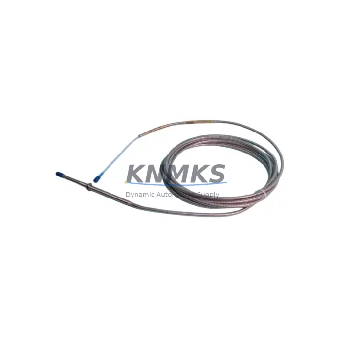
Bently Nevada 330104-13-20-10-02-05 Migration-Ready Proximity Transducer for Legacy Control Systems
The Bently Nevada 330104-13-20-10-02-05 is a 3300 XL NSv Series proximity transducer engineered for seamless integration into legacy vibration monitoring and machinery protection systems. As original equipment reaches end-of-life and OEM support for discontinued models becomes increasingly limited, this transducer serves as a verified migration-ready replacement for aging 3300 Series and early 3500 Series field installations. Whether you are executing a full control cabinet overhaul, restoring a critical rotating machinery protection loop, or extending the operational life of an existing Bently Nevada monitoring platform, the 330104-13-20-10-02-05 delivers the electrical and mechanical compatibility required to minimize engineering rework and reduce total retrofit cost.
This transducer operates within the standard Bently Nevada proximity system architecture, pairing directly with compatible extension cables and Proximitor® signal conditioners. When replacing a legacy 330104 series probe in the field, engineers should verify the existing cable assembly — typically a 330130 or 330180 series extension cable — to confirm connector compatibility and total system length before installation. The Proximitor® sensor, such as the 330180-91-00 or 3300 XL 8mm Proximitor®, must be matched to the transducer gap voltage range and sensitivity specification (nominally 200 mV/mil or 7.87 V/mm) to maintain calibrated output across the full measurement range.
Prior to installation, a complete retrofit checklist should address the following: power supply voltage to the Proximitor® (typically –24 VDC), terminal block wiring continuity from the field junction box to the 3500 rack I/O module, probe-to-target gap setting (typically 50 mils / 1.27 mm for 8 mm probes), and confirmation of the driver card address within the 3500 Series monitoring rack. If the existing system uses a 3300 rack, migration to a 3500/22M or 3500/42M monitor card may be required, and program logic within the associated DCS or safety system — such as a Triconex or Rockwell ControlLogix platform — should be reviewed for any hardcoded channel assignments or alarm setpoint references tied to the legacy transducer’s output range.
For installations where the 330104-13-20-10-02-05 is being introduced as part of a broader machinery protection upgrade, it is common to simultaneously address the condition of the 3500/15 power supply module and the 3500/20 rack interface module. Degraded backplane connectors or aging power distribution within the rack can introduce noise into the proximity measurement chain, masking real vibration events or generating nuisance trips. Replacing the transducer in isolation without auditing the rack infrastructure is a common source of post-retrofit calibration issues.
HMI screen updates are frequently overlooked during proximity transducer replacements. If the plant SCADA or DCS historian is configured to display gap voltage or vibration amplitude from a specific channel tag, the engineering team should confirm that the new transducer’s sensitivity and gap voltage at the nominal operating distance match the values used in the original HMI scaling. Mismatched sensitivity factors will result in incorrect vibration readings displayed to operators, potentially masking developing faults in turbines, compressors, or pump trains.
Communication link integrity between the 3500 rack and the host DCS — whether via Modbus RTU, Modbus TCP, or the Bently Nevada System 1 software platform — should be validated after transducer replacement. A full channel functional test, including OK relay status, alert and danger setpoint verification, and buffered output signal check at the rack terminal, is recommended before returning the machine to service.
Migration Compatibility Table
| Parameter | Detail |
|---|---|
| SKU / Part Number | 330104-13-20-10-02-05 |
| Series | Bently Nevada 3300 XL NSv |
| Probe Type | 8 mm Proximity Transducer |
| Sensitivity | 200 mV/mil (7.87 V/mm) |
| Operating Gap Range | 10–90 mil (0.25–2.29 mm) |
| Supply Voltage | –24 VDC (via Proximitor®) |
| Compatible Extension Cables | 330130, 330180 Series |
| Compatible Proximitor® Sensors | 330180-91-00, 3300 XL 8mm Proximitor® |
| Compatible Monitor Cards | 3500/22M, 3500/42M, 3300 Series |
| Installation Thread | M10 × 1 (standard) |
| Connector Type | 3-pin MIL-C-5015 style |
| Replacement for Legacy Models | 330104-00-20-10-02-05, 330104-13-20-05-02-05 |
| Communication Protocol | Modbus RTU / Modbus TCP / System 1 |
| Retrofit Recommendation | Verify gap, cable length, and Proximitor® model before installation |
| Commissioning Note | Full channel functional test required post-installation |
| Support terms | 12 Months |
Retrofit Planning for Existing Automation Systems
A successful retrofit of the 330104-13-20-10-02-05 into an existing automation system requires a structured approach that accounts for every component in the measurement chain. The transducer itself is only one element; the surrounding infrastructure — including the 330130 series extension cable, the 3300 XL 8mm Proximitor® sensor, the 3500/20 rack interface module, and the 3500/15 power supply — must all be evaluated for compatibility and condition before the replacement is commissioned.
In legacy installations where the original 3300 rack is still in service, the migration path typically involves introducing a 3500 Series rack alongside the existing infrastructure during a planned maintenance window, allowing parallel operation and signal verification before the old rack is decommissioned. This approach preserves the original alarm logic and historian data continuity while the new transducer and associated 3500/22M vibration monitor card are validated against the machine’s baseline vibration signature.
Terminal block wiring should be documented and photographed before any disconnection. The field wiring from the junction box to the rack I/O terminal — typically a shielded twisted pair routed through conduit — must be checked for insulation integrity and shield continuity. Ground loops introduced during rewiring are a frequent source of elevated noise floors in proximity measurement systems and can cause false OK relay dropout or erratic vibration readings.
Where the plant control system includes a Rockwell ControlLogix or Siemens S7 series PLC interfacing with the Bently Nevada rack via Modbus, the PLC program should be reviewed to confirm that channel register addresses and scaling factors are updated to reflect the new transducer’s output characteristics. Failure to update these parameters will result in incorrect process variable values being passed to the DCS historian and any associated safety interlock logic.
Downtime Control During System Migration
Minimizing unplanned downtime during a proximity transducer replacement requires pre-staging all replacement components — including the 330104-13-20-10-02-05 transducer, the appropriate extension cable, and any required Proximitor® sensor — before the maintenance window begins. A pre-tested, bench-verified assembly significantly reduces the risk of discovering compatibility issues after the machine has been taken offline.
Where possible, the replacement transducer should be pre-gapped on a test fixture using a representative target material (typically 4140 steel) to confirm the gap voltage at the nominal installation distance before the probe is installed in the field. This eliminates one of the most common sources of commissioning delays — incorrect gap setting requiring repeated probe adjustment with the machine offline.
Original PLC and DCS program logic should be backed up and archived before any rack modifications are made. If the retrofit involves replacing a 3300 rack with a 3500 Series system, the System 1 configuration database should be exported and preserved. This ensures that alarm setpoints, channel tags, and historian configurations can be restored quickly if the migration encounters unexpected issues.
Field commissioning should follow a structured sequence: power-on verification, OK relay status check, gap voltage measurement at the rack terminal, buffered output signal verification, and finally a full alarm setpoint functional test. Each step should be documented and signed off before the machine is returned to service. A well-executed commissioning sequence for a single-channel proximity replacement can typically be completed within two to four hours, keeping total machine downtime within a planned maintenance window.
Retrofit Support FAQ
Q: Is the 330104-13-20-10-02-05 a direct drop-in replacement for the 330104-00-20-10-02-05?
A: Yes, the 330104-13-20-10-02-05 is dimensionally and electrically compatible with the 330104-00-20-10-02-05 and other variants in the 330104 family. The primary difference is the armor type and cable configuration. Verify the extension cable connector and total system length before installation to confirm full compatibility with your existing Proximitor® sensor.
Q: What pre-shipment testing is performed on this transducer?
A: Each unit undergoes electrical continuity verification, sensitivity calibration check, and connector integrity inspection before shipment. A test report is available upon request. All units are covered by a support terms confirmed by quotation from the date of shipment.
Q: How do I confirm the correct gap setting during installation?
A: Use a calibrated DC voltmeter to measure the Proximitor® output voltage at the rack terminal. For an 8 mm probe with a 4140 steel target, the nominal gap voltage at 50 mils (1.27 mm) is approximately –10.4 VDC. Adjust the probe position until the measured voltage falls within the linear range specified in the Bently Nevada calibration data sheet for your specific Proximitor® model.
Q: What is the lead time and inventory availability?
A: We maintain stock of the 330104-13-20-10-02-05 for immediate shipment. Standard orders ship within 1–3 business days. For urgent requirements or large quantity orders, contact our sales team directly to confirm current inventory levels and expedited shipping options.
© 2026 KNMKS. All rights reserved.
Original Source: https://knmks.com
Contact: admin@knmks.com | +86 18359268345
Product Identification
- Brand / Ecosystem
-
Bently Nevada
Bently Nevada - Model / Series
-
330104-13-20-10-02-05
Bently Nevada 3300 XL / 3301 Series - Product Family
- Sensors
- Availability Status
- Available on request after model and quantity confirmation
- Inquiry Type
- B2B RFQ, replacement inquiry and project spare-part request
- Pre-Quote Check
- Exact SKU, brand, series, quantity, nameplate photos and destination country are checked before quotation
System Path
Where this product fits in the KNMKS automation structure.
Specification & Inquiry Focus
- Sensor range
- Photoelectric, proximity and process sensors
- Common needs
- Output type, distance and connector
- Project support
- Machine detection and replacement inquiry
Buyer Confirmation
Information KNMKS checks before replying.
- Exact model
- 330104-13-20-10-02-05
- Brand / ecosystem
- Bently Nevada
- Product family
- Sensors
- Application note
- Replacement, maintenance, project build or spare-part list
- Useful photos
- Nameplate, installed unit, cabinet layout or connector side
- Delivery details
- Quantity, destination country and target schedule
Document Support
Files and notes can be confirmed during quotation.
- Product photos or nameplate confirmation when available
- Packing and delivery notes before quotation confirmation
- Support scope and delivery terms confirmed per inquiry
- Export document coordination for qualified B2B requests
Inquiry Support
- NPN/PNP, analog and digital output checking
- Connector and cable compatibility review
- Fast inquiry support for maintenance teams
What to Send Us
- Brand and exact model number: Bently Nevada 330104-13-20-10-02-05
- Quantity and required delivery time
- Application, replacement requirement or nameplate photo
- Destination country and shipping preference
RFQ Preparation
This is a product inquiry page built for RFQ communication.
Fast Model Check
Send this model to KNMKS for confirmation.
Include quantity, destination country and photos if this is a maintenance replacement. The inquiry will be saved with a reference number after submission.
Brand & Compatibility Note
KNMKS displays automation product information for well-known industrial brand ecosystems and compatible replacement references. Brand names are used for product identification and compatibility reference only; final availability and commercial terms are confirmed per quotation.
 Manufacturing
 Machine Tools
 Packaging
 Energy & Power



 PLCs & Controllers
 HMI & Displays
 Servo Systems
 Variable Frequency Drives