
Overview
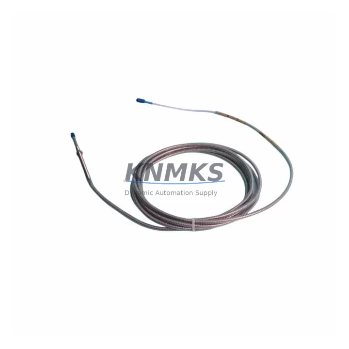
Bently Nevada 330104-10-21-10-02-00 Migration-Ready Proximity Transducer for Legacy Control Systems
The Bently Nevada 330104-10-21-10-02-00 is a 3300 XL Series proximity transducer engineered for direct replacement and retrofit integration into aging vibration monitoring and machinery protection systems. As original equipment reaches end-of-life and OEM support is discontinued, this unit provides a verified drop-in solution that preserves existing wiring, terminal assignments, and signal conditioning infrastructure without requiring full system redesign. Whether you are managing a planned upgrade cycle or responding to an unplanned failure on a critical rotating machine, the 330104-10-21-10-02-00 is stocked and ready to ship with a support terms confirmed by quotation.
Migration Compatibility Table
| Parameter | Details |
|---|---|
| SKU / Part Number | 330104-10-21-10-02-00 |
| Series | Bently Nevada 3300 XL |
| Sensor Type | Eddy-Current Proximity Transducer |
| Output Signal | -18 VDC nominal (compatible with 3300 XL monitor inputs) |
| Cable Length | 10 ft (3.05 m) integral cable |
| Extension Cable Compatibility | 3300 XL Series extension cables (e.g., 330130 series) |
| Driver / Proximitor Compatibility | 3300 XL Proximitor Sensor (e.g., 330180 series) |
| Terminal Wiring | Matches legacy 3300 XL terminal block pinout — no rewiring required |
| Mounting Thread | M10 x 1 (standard 3300 XL bracket compatible) |
| Installation Space | Standard 3300 XL probe holder; confirm radial clearance before installation |
| Firmware / Configuration | No firmware required; hardware-calibrated gap voltage |
| Replacement Recommendation | Direct replacement for discontinued 330104 variants; verify gap setting post-installation |
| Commissioning Note | Set air gap to 50 mil (1.27 mm) nominal; verify OK LED on Proximitor after installation |
| Support terms | 12 Months from date of shipment |
Retrofit Planning for Existing Automation Systems
Successful integration of the 330104-10-21-10-02-00 into a legacy machinery protection architecture requires a structured pre-installation review. Begin by auditing the existing 3300 XL monitor rack to confirm available channel slots and verify that the installed 3300 XL Proximitor Sensor (330180 series) is compatible with the replacement transducer’s output characteristics. In many retrofit scenarios, the Proximitor remains serviceable even when the probe itself has failed, which significantly reduces replacement scope and cost.
Next, inspect the 330130 Series extension cable connecting the probe to the Proximitor. Extension cables are a common point of degradation in long-service installations — check for insulation cracking, connector corrosion, and continuity before reusing. If the extension cable is being replaced simultaneously, confirm that the combined cable length (probe integral cable plus extension) falls within the 3300 XL system’s specified range to maintain calibration accuracy.
For installations where the 3300 XL monitor rack itself is being modernized, consider whether the existing 3500/42M Proximitor I/O Module or a comparable 3500 Series I/O card is already present in the control cabinet. Many facilities running parallel migration projects choose to upgrade the monitor rack to the 3500 platform while retaining 3300 XL-compatible probes during a transitional period, using the 330104-10-21-10-02-00 as a bridge solution that maintains signal integrity across both generations.
Power supply capacity is another critical checkpoint. Confirm that the rack’s 3500/15 Power Supply Module or equivalent can support the additional transducer load if channels are being added during the retrofit. Overloaded power supplies are a leading cause of intermittent signal faults that are difficult to diagnose after installation. Document the current draw of all active channels before adding new probes.
If the control system communicates vibration data upstream to a DCS or SCADA platform via a 3500/92 Communication Gateway or similar Modbus/TCP interface, verify that the channel mapping and tag assignments in the gateway configuration reflect the new probe’s physical location. Incorrect tag mapping can cause alarm suppression or false trips in the supervisory system without generating any fault indication at the monitor level. All configuration changes should be documented and backed up before the retrofit window begins.
Finally, confirm that the HMI faceplate or operator display associated with the affected machine train correctly reflects the probe’s measurement axis (X or Y) and engineering units. Mismatched display configurations are a common source of post-retrofit confusion during the first operational period after restart.
Downtime Control During System Migration
Minimizing unplanned downtime during a proximity transducer replacement requires preparation that begins well before the maintenance window opens. The 330104-10-21-10-02-00 should be bench-tested prior to installation: connect the probe to a known-good Proximitor, apply the correct supply voltage, and verify the OK output and gap voltage at the nominal 50 mil air gap. This pre-installation verification eliminates the risk of installing a transit-damaged unit and discovering the fault only after the machine is reassembled.
Before removing the existing probe, record the current gap voltage reading from the monitor display or the Proximitor’s test point. This baseline value allows the technician to set the replacement probe to an identical gap during installation, reducing the time required for gap adjustment and re-verification. If the original gap voltage was outside the nominal range, this is also the opportunity to correct the installation geometry.
Preserve the original program logic and alarm setpoints in the 3300 XL or 3500 Series monitor by exporting the configuration before the maintenance window. Most 3500 Series monitors support configuration upload via the System 1 software or a direct serial connection; ensure this backup is stored on a local drive and not solely on a network share that may be inaccessible during the outage. Restoring a known-good configuration after probe replacement is significantly faster than manually re-entering setpoints under time pressure.
For critical machines where even brief signal interruption is unacceptable, coordinate with the control room to place the affected channel in bypass mode before disconnecting the probe. This prevents nuisance trips during the swap and maintains overall system availability. Document the bypass activation and deactivation times in the maintenance record. Once the replacement probe is installed and the gap is verified, remove the bypass and confirm that the monitor returns to normal OK status before releasing the machine for restart.
Retrofit Support FAQ
Q: Is the 330104-10-21-10-02-00 a direct replacement for other 330104 suffix variants?
A: The 330104 series uses suffix codes to specify cable length, connector type, and temperature rating. The -10-21-10-02-00 configuration specifies a 10 ft integral cable with standard connectors. Before substituting a different suffix variant, confirm that the cable length and connector type are compatible with your existing Proximitor and extension cable. In most cases, the electrical output characteristics are identical across suffix variants, but physical fit must be verified on-site.
Q: What commissioning steps are required after installation?
A: After securing the probe in the holder and connecting the extension cable, apply power to the Proximitor and adjust the probe gap until the OK LED illuminates and the gap voltage reads within the system’s specified OK range (typically -10 VDC to -18 VDC for 3300 XL systems). Record the final gap voltage, verify that the monitor channel displays a valid vibration reading, and confirm that no alarms are active before returning the machine to service. A full vibration baseline reading at normal operating speed is recommended to establish a post-retrofit reference.
Q: How is the unit tested before shipment?
A: Each 330104-10-21-10-02-00 unit undergoes functional verification prior to shipment, including output signal check and connector integrity inspection. Units are packaged to prevent transit damage to the probe tip and cable assembly. A test report is available upon request for critical applications.
Q: What does the support terms confirmed by quotation cover?
A: The support terms confirmed by quotation cover manufacturing defects and functional failures under normal operating conditions from the date of shipment. It does not cover damage resulting from incorrect installation, gap setting errors, electrical overstress, or mechanical impact. Support requests are processed promptly with replacement units dispatched from stock to minimize your system downtime.
© 2026 KNMKS. All rights reserved.
Original Source: https://knmks.com
Contact: admin@knmks.com | +86 18359268345
Product Identification
- Brand / Ecosystem
-
Bently Nevada
Bently Nevada - Model / Series
-
330104-10-21-10-02-00
Bently Nevada 3300 XL / 3301 Series - Product Family
- Sensors
- Availability Status
- Available on request after model and quantity confirmation
- Inquiry Type
- B2B RFQ, replacement inquiry and project spare-part request
- Pre-Quote Check
- Exact SKU, brand, series, quantity, nameplate photos and destination country are checked before quotation
System Path
Where this product fits in the KNMKS automation structure.
Specification & Inquiry Focus
- Sensor range
- Photoelectric, proximity and process sensors
- Common needs
- Output type, distance and connector
- Project support
- Machine detection and replacement inquiry
Buyer Confirmation
Information KNMKS checks before replying.
- Exact model
- 330104-10-21-10-02-00
- Brand / ecosystem
- Bently Nevada
- Product family
- Sensors
- Application note
- Replacement, maintenance, project build or spare-part list
- Useful photos
- Nameplate, installed unit, cabinet layout or connector side
- Delivery details
- Quantity, destination country and target schedule
Document Support
Files and notes can be confirmed during quotation.
- Product photos or nameplate confirmation when available
- Packing and delivery notes before quotation confirmation
- Support scope and delivery terms confirmed per inquiry
- Export document coordination for qualified B2B requests
Inquiry Support
- NPN/PNP, analog and digital output checking
- Connector and cable compatibility review
- Fast inquiry support for maintenance teams
What to Send Us
- Brand and exact model number: Bently Nevada 330104-10-21-10-02-00
- Quantity and required delivery time
- Application, replacement requirement or nameplate photo
- Destination country and shipping preference
RFQ Preparation
This is a product inquiry page built for RFQ communication.
Fast Model Check
Send this model to KNMKS for confirmation.
Include quantity, destination country and photos if this is a maintenance replacement. The inquiry will be saved with a reference number after submission.
Brand & Compatibility Note
KNMKS displays automation product information for well-known industrial brand ecosystems and compatible replacement references. Brand names are used for product identification and compatibility reference only; final availability and commercial terms are confirmed per quotation.
 Manufacturing
 Machine Tools
 Packaging
 Energy & Power



 PLCs & Controllers
 HMI & Displays
 Servo Systems
 Variable Frequency Drives