
Overview
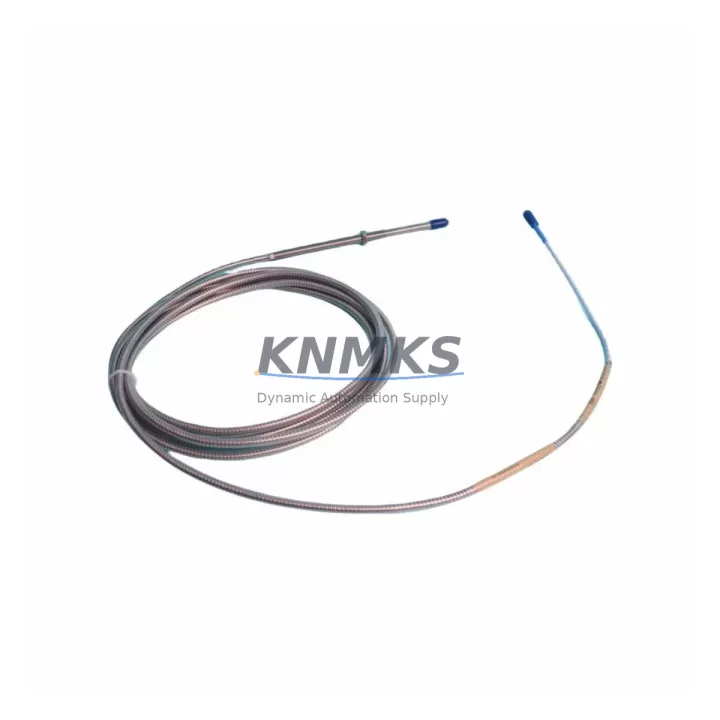
Bently Nevada 330104-10-20-10-02-CN Migration-Ready Proximity Transducer for Legacy Control Systems
The Bently Nevada 330104-10-20-10-02-CN is an 8mm eddy current proximity transducer from the 3300 XL series, engineered for continuous shaft vibration and position monitoring in rotating machinery. As legacy Bently Nevada 3300 series installations reach end-of-life or face discontinued spare part availability, the 330104-10-20-10-02-CN has become a critical retrofit component for engineers tasked with modernizing turbine control panels, compressor monitoring racks, and legacy DCS-integrated vibration systems without full platform replacement.
This transducer is a direct migration-ready replacement for obsolete 330104 series variants previously installed in 3300 XL monitor racks. It maintains the same 8mm tip diameter, standard 5-meter extension cable interface, and -24 VDC bias voltage output, ensuring backward compatibility with existing Bently Nevada 3300/16 monitors, 3500/42M proximity I/O modules, and legacy ADRE data acquisition systems. Engineers upgrading from earlier 330100 or 330103 series transducers will find the 330104-10-20-10-02-CN a drop-in solution with minimal rewiring.
Migration Compatibility Table
| Parameter | 330104-10-20-10-02-CN | Legacy 330103 / 330100 Series | Retrofit Notes |
|---|---|---|---|
| Tip Diameter | 8 mm | 8 mm | Direct mechanical fit; no bracket modification required |
| Cable Length | 1.0 m (extension to 5 m standard) | 1.0 m | Verify extension cable 330130-080-00-00 compatibility |
| Bias Voltage Output | -24 VDC nominal | -24 VDC nominal | Compatible with 3300/16 and 3500/42M monitor inputs |
| Sensitivity | 7.87 V/mm (200 mV/mil) | 7.87 V/mm | No monitor rescaling required |
| Linear Range | 0.25 – 2.26 mm | 0.25 – 2.26 mm | Gap setting unchanged; verify with gap voltage check |
| Thread / Mounting | M10 x 1.0 | M10 x 1.0 | Standard probe holder compatible |
| Communication / Signal | Analog voltage (passive) | Analog voltage (passive) | No protocol migration needed; signal wiring unchanged |
| Monitor Compatibility | 3300/16, 3500/42M, 3500/40M | 3300/16 | Expanded compatibility with 3500 series rack monitors |
| Installation Space | Standard probe holder | Standard probe holder | Confirm clearance in confined bearing housings |
| Firmware / Configuration | N/A (passive sensor) | N/A | No firmware update required on monitor side |
| Support terms | support terms confirmed by quotation | Covered from date of shipment; includes functional verification | |
Retrofit Planning for Existing Automation Systems
Successful integration of the 330104-10-20-10-02-CN into a legacy vibration monitoring system requires a structured pre-installation review. Begin by auditing the existing rack configuration: confirm whether the installed monitor is a Bently Nevada 3300/16 Dual Vibration Monitor or a newer 3500/42M Proximitor I/O Module, as both accept the same transducer signal but differ in channel configuration and alarm setpoint storage. If the site is running a 3500 series rack, verify that the 3500/42M module firmware is at a revision level that supports the 330104 transducer family — this is typically confirmed via the System 1 configuration software or the rack’s front-panel display.
Terminal wiring is straightforward: the 330104-10-20-10-02-CN uses a standard coaxial signal path through the 330130 series extension cable to the Proximitor driver. When replacing a failed transducer in the field, label and photograph the existing terminal connections on the junction box before disconnection. The driver output connects to the monitor’s SIG and COM terminals; polarity errors at this stage will produce an upscale or downscale gap voltage fault that can be misread as a machinery alarm.
For sites migrating from a legacy DCS integration — such as a Honeywell TDC 3000 or ABB Advant OCS platform receiving 4–20 mA converted vibration signals — confirm that the signal conditioning module between the Bently Nevada monitor and the DCS analog input card remains unchanged. The 330104-10-20-10-02-CN does not alter the monitor’s output signal format, so existing 4–20 mA transmitter cards or SNAP-AIV5 analog input modules in the DCS rack do not require reconfiguration.
When the retrofit involves an I/O expansion — for example, adding a second measurement plane on a compressor shaft — engineers should plan for an additional 3500/42M channel slot in the rack and a corresponding 330130-080-00-00 extension cable routed to the new probe location. Confirm available rack slots in the 3500 series backplane before ordering. If the existing backplane is fully populated, a secondary 3500 rack with a 3500/05 power supply module may be required to support the expanded channel count.
HMI screen updates are often overlooked during transducer replacements. If the site uses a GE iFIX, Wonderware InTouch, or Siemens WinCC SCADA system displaying vibration trend data, verify that the tag mapping from the Bently Nevada monitor to the OPC server remains intact after the replacement. A gap voltage verification test — performed with the machine at rest — should be completed and logged before returning the system to service, confirming the new transducer reads within the expected -10 to -18 VDC gap voltage window.
Downtime Control During System Migration
Minimizing unplanned downtime during a proximity transducer replacement is achievable with disciplined pre-staging and a clear commissioning sequence. Before the maintenance window opens, pre-configure the replacement 330104-10-20-10-02-CN by verifying its gap voltage output on a bench test fixture using a Bently Nevada 330180 proximitor driver and a calibrated target disk. This confirms the transducer is functional before it enters the machine, eliminating the risk of installing a defective unit and extending the outage.
During the replacement window, the original program logic in the 3500 series monitor — including alarm setpoints, danger levels, and time-delay settings — is stored in non-volatile memory and is not affected by transducer removal. This means the control system’s protective logic remains intact throughout the swap, and no setpoint re-entry is required after installation. However, if the site’s System 1 software is configured to log a configuration change event, ensure the maintenance team acknowledges this event to prevent a false configuration-mismatch alarm from triggering a shutdown interlock.
For critical machinery where even a brief monitoring gap is unacceptable, consider a temporary bypass of the vibration channel through the 3500 monitor’s front-panel bypass switch while the transducer is being replaced. Document the bypass activation and deactivation times in the site’s maintenance log. Once the new 330104-10-20-10-02-CN is installed and the gap voltage is confirmed within specification, remove the bypass and verify that the monitor returns to normal operation with no latched alarms before restarting the machine.
Post-installation, run the machine at low speed and observe the vibration trend on the SCADA or System 1 display for a minimum of 15 minutes before returning to full operating speed. This confirms that the transducer is correctly seated, the gap is stable, and the signal path through the extension cable and proximitor driver is free of noise or intermittent faults — protecting both the equipment and the continuity of the production process.
Retrofit Support FAQ
Q1: Is the 330104-10-20-10-02-CN a direct replacement for the discontinued 330103-00-08-10-02-CN?
Yes. The 330104-10-20-10-02-CN is the current production replacement for the discontinued 330103 series 8mm transducers. It shares the same mechanical dimensions, sensitivity, linear range, and bias voltage output. No monitor reconfiguration or setpoint adjustment is required when substituting the 330104 for the 330103 in an existing 3300/16 or 3500/42M installation.
Q2: What commissioning checks are required after installation?
Perform a static gap voltage measurement with the machine at rest. The gap voltage should read between -10 VDC and -18 VDC at the nominal installation gap (typically 1.0–1.5 mm for most shaft applications). Confirm the reading at the monitor’s front-panel meter or via System 1 software. Record the gap voltage in the maintenance log and verify that no gap fault or not-OK alarm is active before releasing the machine to operations.
Q3: Can this transducer be used with a 3500/40M Thrust Position Monitor?
Yes. The 330104-10-20-10-02-CN is compatible with the 3500/40M Thrust Position Monitor when used in thrust measurement applications. Confirm the monitor’s configuration in System 1 to ensure the channel is set for the correct transducer type and that the thrust position alarm setpoints reflect the mechanical clearances of the specific machine being monitored.
Q4: What does the support terms confirmed by quotation cover, and how is stock availability managed?
All units are covered by a support terms confirmed by quotation from the date of shipment, covering manufacturing defects and functional failures under normal operating conditions. Each unit undergoes pre-shipment functional verification including gap voltage output, cable continuity, and sensitivity checks. Stock is maintained for immediate dispatch to support urgent replacement and system recovery scenarios. Contact admin@knmks.com or +86 18359268345 for lead time confirmation and bulk order availability.
© 2026 KNMKS. All rights reserved.
Original Source: https://knmks.com
Contact: admin@knmks.com | +86 18359268345
Product Identification
- Brand / Ecosystem
-
Bently Nevada
Bently Nevada - Model / Series
-
330104-10-20-10-02-CN
Bently Nevada 3300 XL / 3301 Series - Product Family
- Sensors
- Availability Status
- Available on request after model and quantity confirmation
- Inquiry Type
- B2B RFQ, replacement inquiry and project spare-part request
- Pre-Quote Check
- Exact SKU, brand, series, quantity, nameplate photos and destination country are checked before quotation
System Path
Where this product fits in the KNMKS automation structure.
Specification & Inquiry Focus
- Sensor range
- Photoelectric, proximity and process sensors
- Common needs
- Output type, distance and connector
- Project support
- Machine detection and replacement inquiry
Buyer Confirmation
Information KNMKS checks before replying.
- Exact model
- 330104-10-20-10-02-CN
- Brand / ecosystem
- Bently Nevada
- Product family
- Sensors
- Application note
- Replacement, maintenance, project build or spare-part list
- Useful photos
- Nameplate, installed unit, cabinet layout or connector side
- Delivery details
- Quantity, destination country and target schedule
Document Support
Files and notes can be confirmed during quotation.
- Product photos or nameplate confirmation when available
- Packing and delivery notes before quotation confirmation
- Support scope and delivery terms confirmed per inquiry
- Export document coordination for qualified B2B requests
Inquiry Support
- NPN/PNP, analog and digital output checking
- Connector and cable compatibility review
- Fast inquiry support for maintenance teams
What to Send Us
- Brand and exact model number: Bently Nevada 330104-10-20-10-02-CN
- Quantity and required delivery time
- Application, replacement requirement or nameplate photo
- Destination country and shipping preference
RFQ Preparation
This is a product inquiry page built for RFQ communication.
Fast Model Check
Send this model to KNMKS for confirmation.
Include quantity, destination country and photos if this is a maintenance replacement. The inquiry will be saved with a reference number after submission.
Brand & Compatibility Note
KNMKS displays automation product information for well-known industrial brand ecosystems and compatible replacement references. Brand names are used for product identification and compatibility reference only; final availability and commercial terms are confirmed per quotation.
 Manufacturing
 Machine Tools
 Packaging
 Energy & Power



 PLCs & Controllers
 HMI & Displays
 Servo Systems
 Variable Frequency Drives