
Overview
Bently Nevada 330104-10-13-05-02-CN Migration-Ready Proximity Transducer for Legacy Control Systems
The Bently Nevada 330104-10-13-05-02-CN is a migration-ready 8mm proximity transducer engineered for seamless integration into existing 3300 XL vibration monitoring systems. As legacy Bently Nevada platforms approach end-of-life and OEM spare parts become increasingly scarce, this unit provides a verified drop-in replacement path that preserves original wiring configurations, signal conditioning parameters, and machinery protection logic without requiring a full system overhaul.
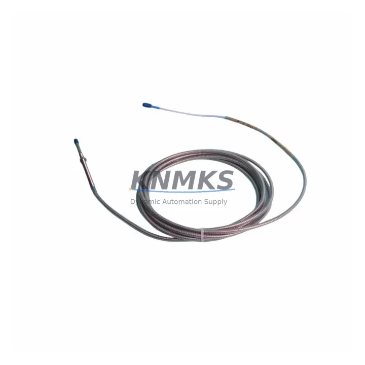
Designed for rotating machinery protection in turbines, compressors, pumps, and motors, the 330104-10-13-05-02-CN operates on the standard Bently Nevada eddy-current sensing principle with a 5-metre armoured extension cable and CN-series driver. Its output sensitivity of 7.87 V/mm (200 mV/mil) is fully compatible with the 3300 XL monitor cards, meaning no recalibration of gap voltage setpoints or alarm thresholds is required during the retrofit process. Engineers replacing a failed or obsolete unit can maintain the existing -10.36 Vdc nominal gap voltage and continue operating within the established machinery protection envelope.
When planning a retrofit around the 330104-10-13-05-02-CN, the first step is to verify the existing terminal block wiring against the original loop drawing. The three-wire coaxial assembly — probe body, extension cable, and proximitor driver — must be matched in total cable length to preserve system sensitivity. If the installed proximitor is a 330180 series driver, it is directly interchangeable with the CN driver supplied with this unit. For installations where the monitor card is a 3300/16 or 3300/20 series, confirm that the channel configuration in the System 1 software reflects the correct transducer type before energising the loop.
Backplane and rack compatibility is a critical checkpoint in any 3300 XL migration. The 330104-10-13-05-02-CN connects to the field wiring terminal block on the monitor card front panel; no backplane modification is required. However, if the host rack is being upgraded from a 3300 series to a 3500 series platform as part of a broader modernisation programme, engineers should note that the 3500/42M Proximitor Monitor accepts the same transducer family, allowing the probe and cable assembly to be reused while only the monitor card and rack are replaced. This approach significantly reduces field wiring labour and minimises the risk of introducing new cable routing errors during the migration.
Power supply capacity is another factor that must be confirmed before commissioning. The 3300 XL power supply module — typically a 3300/05 or equivalent — must provide sufficient headroom to support all active channels simultaneously. Adding replacement transducer channels to a partially populated rack should not present capacity issues, but a full rack populated with 3300/16 dual-channel cards should be audited against the power supply’s rated output current before the retrofit is finalised.
For sites undertaking a phased migration from a legacy 3300 system to a modern 3500 platform, the 330104-10-13-05-02-CN can serve as an interim solution that keeps critical machinery online while the new rack infrastructure is commissioned in parallel. The probe and cable assembly can be transferred to the new 3500 rack once the System 1 configuration has been validated, avoiding a hard cutover that would require extended machinery downtime. During this transition period, the existing HMI displays and alarm annunciation logic can remain active on the legacy system, with the new system running in shadow mode until full confidence is established.
Firmware compatibility should also be reviewed when integrating this transducer into a System 1 condition monitoring environment. Ensure that the System 1 software version installed on the data acquisition server supports the transducer type code associated with the 330104 series. Older System 1 versions may require a patch update to correctly identify the CN driver variant in the channel configuration wizard. This is a straightforward software update that does not affect the physical installation but must be completed before the channel can be placed in service.
All units are pre-tested prior to shipment using a calibrated gap simulator to verify output linearity across the full measurement range. Each assembly is supplied with a test certificate confirming sensitivity, gap voltage, and cable continuity. Stock is maintained for immediate dispatch, supporting urgent breakdown replacement scenarios where machinery downtime must be minimised. A support terms confirmed by quotation cover all units against manufacturing defects, with technical support available for installation and commissioning queries.
Migration Compatibility Table
| Parameter | 330104-10-13-05-02-CN | Notes / Retrofit Guidance |
|---|---|---|
| Probe Diameter | 8 mm | Fits standard 3300 XL probe holder; no bracket modification required |
| Extension Cable Length | 5 m (16.4 ft) | Total system cable length must match original installation for sensitivity accuracy |
| Driver / Proximitor | CN Series (330180 compatible) | Direct replacement for 330180 series drivers; verify terminal labelling |
| Output Sensitivity | 7.87 V/mm (200 mV/mil) | No recalibration of monitor card setpoints required |
| Nominal Gap Voltage | -10.36 Vdc | Maintain existing gap setting; verify with voltmeter before commissioning |
| Monitor Compatibility | 3300/16, 3300/20, 3500/42M | Compatible across 3300 XL and 3500 series monitor cards |
| Power Supply Requirement | -24 Vdc (supplied by monitor rack) | Confirm 3300/05 power supply headroom for full rack population |
| Installation Space | Standard 3300 XL probe holder | No additional clearance required; same footprint as original |
| Communication Protocol | Analogue (4–20 mA / voltage output via monitor card) | System 1 Modbus/OPC interface unaffected; no protocol migration needed |
| Firmware Compatibility | System 1 v5.x and above | Verify transducer type code support; apply patch if using older System 1 version |
| Support terms | 12 Months | Covers manufacturing defects; test certificate included with each unit |
Retrofit Planning for Existing Automation Systems
A successful retrofit centred on the 330104-10-13-05-02-CN requires a structured approach to component verification across the entire signal chain. Beginning at the field end, the probe body must be inspected for thread condition and the existing probe holder checked for concentricity before the new assembly is installed. The armoured extension cable should be routed through the original conduit path, avoiding sharp bends that could affect the coaxial impedance and introduce measurement error.
At the junction box or marshalling panel, the terminal block connections for the probe, extension cable, and proximitor driver should be labelled and photographed before disconnection. The 330180 series proximitor driver — if present in the existing installation — can be retained and reused with the new probe and cable assembly, reducing the scope of the replacement to the probe body and extension cable only. This is a common approach in partial retrofit scenarios where the driver is mounted in an accessible location and shows no signs of degradation.
Inside the control cabinet, the 3300 XL monitor card channel configuration should be reviewed in the System 1 software before the new transducer is energised. The channel should be placed in bypass mode during the physical installation to prevent spurious alarms from reaching the machinery protection relay outputs. Once the transducer is installed and the gap voltage has been set to the nominal -10.36 Vdc value, the channel can be released from bypass and the alarm setpoints verified against the machinery manufacturer’s vibration limits.
For sites where the control architecture includes a DCS or SCADA system receiving vibration data from the 3300 XL rack via a 3300/93 communication gateway or a System 1 OPC server, the data tags and engineering unit scaling should be confirmed after the replacement is complete. The 330104-10-13-05-02-CN produces an identical output characteristic to the original unit, so no tag rescaling should be required, but a live data comparison between the new channel reading and an adjacent reference channel is recommended as a final commissioning check.
Where the retrofit is part of a broader control system upgrade that includes replacing the 3300 XL rack with a 3500 series platform, the migration plan should also account for the 3500/20 rack power supply, the 3500/22M transient data interface, and the updated System 1 configuration database. The 330104-10-13-05-02-CN probe and cable assembly can be carried forward into the new rack without modification, providing continuity of the field installation investment while the monitoring infrastructure is modernised.
Downtime Control During System Migration
Minimising unplanned downtime during a proximity transducer replacement requires careful pre-staging of all replacement components and a clearly defined switching sequence. Before the machinery is taken offline, the replacement 330104-10-13-05-02-CN assembly should be bench-tested using a portable gap simulator to confirm output sensitivity and cable continuity. This pre-commissioning step eliminates the risk of discovering a defective replacement unit after the machinery has already been shut down.
The original program logic in the machinery protection system should be preserved throughout the replacement process. The 3300 XL monitor card retains its configuration in non-volatile memory, so a channel card swap does not require reprogramming of alarm setpoints or relay output assignments. If the monitor card itself is being replaced as part of the retrofit, the System 1 configuration backup should be verified before the old card is removed, ensuring that the channel parameters can be restored to the new card without manual re-entry.
For critical machinery where continuous monitoring is required, a temporary portable vibration analyser can be connected to the probe output during the transition period to maintain visibility of shaft vibration levels while the permanent monitoring channel is out of service. This approach is particularly valuable in applications where the machinery cannot be taken offline for an extended period and the replacement must be completed within a narrow maintenance window.
Field commissioning should follow a structured sequence: gap voltage verification, alarm setpoint confirmation, relay output function test, and System 1 data tag validation. Each step should be documented on a commissioning record that is retained with the equipment history file. The support terms confirmed by quotation on the 330104-10-13-05-02-CN provides assurance that any latent defects identified during the initial operating period will be addressed without additional cost, supporting the overall risk management objectives of the retrofit programme.
Retrofit Support FAQ
Q1: Is the 330104-10-13-05-02-CN a direct drop-in replacement for the original Bently Nevada unit?
Yes. The 330104-10-13-05-02-CN is manufactured to the same dimensional and electrical specifications as the original Bently Nevada unit. The probe body, extension cable, and CN driver are fully interchangeable with the original assembly. No modification to the probe holder, terminal block wiring, or monitor card configuration is required for a standard replacement.
Q2: What commissioning checks are required after installation?
After physical installation, verify the gap voltage at the proximitor driver output terminals using a calibrated digital voltmeter. The nominal gap voltage should read -10.36 Vdc ± 0.5 Vdc with the probe positioned at the manufacturer-specified gap distance from the target shaft. Confirm that the System 1 channel is reading a live vibration value consistent with adjacent channels before releasing the channel from bypass mode.
Q3: Can this unit be used with a 3500 series monitor card if we are upgrading our rack?
Yes. The 330104-10-13-05-02-CN is compatible with the 3500/42M Proximitor Monitor card. The probe and cable assembly can be connected directly to the 3500 series field wiring terminal block using the same wiring configuration as the 3300 XL installation. The System 1 configuration for the new 3500 channel should be set to the 330104 transducer type to ensure correct sensitivity scaling.
Q4: What is the support terms coverage and what does the shipment include?
Each 330104-10-13-05-02-CN unit is supplied with a support terms confirmed by quotation covering manufacturing defects in materials and workmanship. The shipment includes the probe body, 5-metre armoured extension cable, CN series proximitor driver, and a pre-shipment test certificate confirming output sensitivity and cable continuity. Stock is available for immediate dispatch to support urgent breakdown replacement requirements. Contact admin@knmks.com or +86 18359268345 for availability and lead time confirmation.
© 2026 KNMKS. All rights reserved.
Original Source: https://knmks.com
Contact: admin@knmks.com | +86 18359268345
Product Identification
- Brand / Ecosystem
-
Bently Nevada
Bently Nevada - Model / Series
-
330104-10-13-05-02-CN
Bently Nevada 3300 XL / 3301 Series - Product Family
- Sensors
- Availability Status
- Available on request after model and quantity confirmation
- Inquiry Type
- B2B RFQ, replacement inquiry and project spare-part request
- Pre-Quote Check
- Exact SKU, brand, series, quantity, nameplate photos and destination country are checked before quotation
System Path
Where this product fits in the KNMKS automation structure.
Specification & Inquiry Focus
- Sensor range
- Photoelectric, proximity and process sensors
- Common needs
- Output type, distance and connector
- Project support
- Machine detection and replacement inquiry
Buyer Confirmation
Information KNMKS checks before replying.
- Exact model
- 330104-10-13-05-02-CN
- Brand / ecosystem
- Bently Nevada
- Product family
- Sensors
- Application note
- Replacement, maintenance, project build or spare-part list
- Useful photos
- Nameplate, installed unit, cabinet layout or connector side
- Delivery details
- Quantity, destination country and target schedule
Document Support
Files and notes can be confirmed during quotation.
- Product photos or nameplate confirmation when available
- Packing and delivery notes before quotation confirmation
- Support scope and delivery terms confirmed per inquiry
- Export document coordination for qualified B2B requests
Inquiry Support
- NPN/PNP, analog and digital output checking
- Connector and cable compatibility review
- Fast inquiry support for maintenance teams
What to Send Us
- Brand and exact model number: Bently Nevada 330104-10-13-05-02-CN
- Quantity and required delivery time
- Application, replacement requirement or nameplate photo
- Destination country and shipping preference
RFQ Preparation
This is a product inquiry page built for RFQ communication.
Fast Model Check
Send this model to KNMKS for confirmation.
Include quantity, destination country and photos if this is a maintenance replacement. The inquiry will be saved with a reference number after submission.
Brand & Compatibility Note
KNMKS displays automation product information for well-known industrial brand ecosystems and compatible replacement references. Brand names are used for product identification and compatibility reference only; final availability and commercial terms are confirmed per quotation.
 Manufacturing
 Machine Tools
 Packaging
 Energy & Power



 PLCs & Controllers
 HMI & Displays
 Servo Systems
 Variable Frequency Drives