
Overview
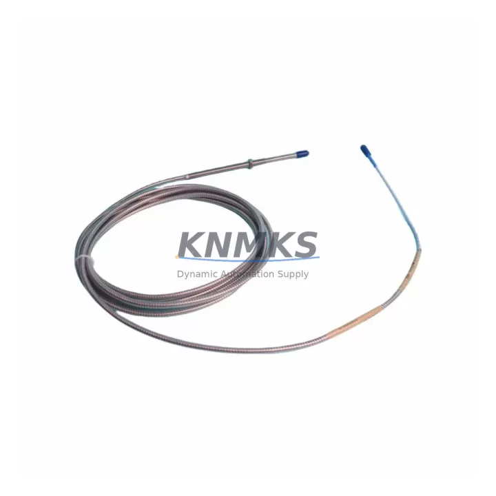
Bently Nevada 330104-09-20-50-02-00 Migration-Ready Proximity Transducer for Legacy Control Systems
The Bently Nevada 330104-09-20-50-02-00 is a 3300 XL Series 8mm eddy-current proximity transducer engineered for direct replacement in legacy vibration monitoring and machinery protection systems. As industrial facilities face increasing pressure to extend the operational life of aging control infrastructure while maintaining compliance with API 670 machinery protection standards, this transducer provides a verified drop-in solution for plants running obsolete or end-of-life Bently Nevada 3300 Series hardware. Whether you are managing a planned turnaround, responding to an unplanned failure, or executing a phased migration from a legacy monitoring rack to a modern System 1 or 3500 Series platform, the 330104-09-20-50-02-00 delivers the dimensional compatibility, output signal characteristics, and installation geometry required to restore system integrity with minimal downtime.
The transducer operates on the standard Bently Nevada eddy-current principle, generating a DC voltage output proportional to the gap between the probe tip and the observed rotating shaft. With an 8mm probe tip diameter, a 5-metre armored extension cable, and a -24 VDC bias voltage output at the standard 200 mV/mil (7.87 V/mm) scale factor, the 330104-09-20-50-02-00 is electrically and mechanically interchangeable with the earlier 330104 family variants used across compressors, turbines, pumps, and gearboxes in petrochemical, power generation, and heavy manufacturing environments. Before installation, engineers should confirm that the existing proximitor or driver module — typically a 3300 XL 8mm Proximitor such as the 330180-X1-05 — is calibrated to match the transducer’s scale factor and gap voltage range. Mismatched proximitor firmware or an uncalibrated driver will produce erroneous vibration readings and may trigger spurious shutdowns on the machinery protection relay.
When retrofitting into an existing 3300 Series monitoring rack, technicians must verify the available slot count and backplane connector pinout before removing the legacy transducer assembly. The 3300 Series rack accepts both the standard and extended-range proximitor cards, and the physical connector on the field wiring terminal block must be confirmed against the new transducer’s cable termination type. If the plant is simultaneously upgrading the monitoring rack from a 3300 Series chassis to a 3500 Series modular rack, the 330104-09-20-50-02-00 transducer remains compatible provided the corresponding 3500/42M Proximitor I/O Module is configured for 8mm probe operation. The 3500 platform’s configuration software requires the probe type, scale factor, and OK limit thresholds to be re-entered during commissioning, and the original 3300 Series configuration files are not directly importable — a manual parameter transfer is required.
For facilities operating Bently Nevada System 1 condition monitoring software, the transducer data path runs from the field probe through the proximitor, into the 3500 rack’s communication gateway, and then via Ethernet or Modbus TCP to the System 1 server. During migration, the I/O channel mapping in System 1 must be updated to reflect the new rack slot assignments, and any HMI trend displays or alarm setpoint screens referencing the old channel addresses will require reconfiguration. Plants using third-party DCS or SCADA systems — such as Emerson DeltaV, Honeywell Experion, or Yokogawa CENTUM — connected to the Bently Nevada rack via Modbus RTU or 4–20 mA hardwired outputs should audit the signal scaling and alarm threshold values in the DCS tag database before cutover to ensure continuity of the machinery protection logic.
Migration Compatibility Table
| Parameter | 330104-09-20-50-02-00 (This Unit) | Legacy / Replaced Models | Notes |
|---|---|---|---|
| Probe Tip Diameter | 8 mm | 8 mm (330104 family) | Direct dimensional fit; no bracket modification required |
| Cable Length | 5 m (standard) | 5 m / 9 m variants | Confirm cable run length before ordering; 9 m variant available |
| Scale Factor | 200 mV/mil (7.87 V/mm) | 200 mV/mil | Must match proximitor calibration; verify 330180 driver setting |
| Supply Voltage | -24 VDC (from proximitor) | -24 VDC | Confirm power supply capacity in existing rack; no change required |
| Output Bias Voltage | -10.0 VDC nominal at 1.0 mm gap | -10.0 VDC | Re-gap after installation; target gap per OEM specification |
| Connector Type | Standard BNC / coaxial | BNC coaxial | Verify field wiring terminal block connector compatibility |
| Rack Compatibility | 3300 Series, 3500 Series | 3300 Series | 3500 requires 3500/42M I/O module configured for 8mm probe |
| Communication Protocol | Analog (4–20 mA / mV output) | Analog | Modbus/Ethernet via rack gateway; no transducer-level protocol change |
| Installation Space | Standard 3300 probe holder | Standard 3300 probe holder | Confirm clearance for armored cable routing in control cabinet |
| Firmware Compatibility | N/A (passive transducer) | N/A | Proximitor firmware version must support 8mm probe type |
| Replacement Recommendation | Direct replacement for 330104-09-20-50-02-00 and compatible 330104 variants | Confirm full part number match including suffix codes | |
| Support terms | support terms confirmed by quotation — covers manufacturing defects; includes pre-shipment functional test report | ||
Retrofit Planning for Existing Automation Systems
A successful retrofit of the 330104-09-20-50-02-00 into an aging machinery protection system begins well before the maintenance window opens. The first step is a full audit of the existing monitoring rack to identify which proximitor cards, power supply modules, and I/O termination assemblies are still within their rated service life. In a typical 3300 Series installation, the rack houses multiple proximitor channels alongside dedicated power supply modules that distribute -24 VDC to each transducer loop. If the power supply module is approaching end-of-life or is already showing voltage ripple outside specification, replacing the transducer alone will not restore system accuracy — the power supply must be addressed concurrently.
The 330180-X1-05 8mm Proximitor is the standard driver module paired with the 330104 transducer family. During a retrofit, the proximitor should be inspected for connector corrosion, verified for correct scale factor configuration, and tested for OK relay output function before the new transducer is connected. If the plant is also upgrading the rack to the 3500 Series platform, the 3500/42M Proximitor I/O Module replaces the individual 3300 proximitor cards and consolidates multiple channels onto a single backplane slot, which changes the wiring termination layout and requires updated channel addressing in the monitoring software.
For plants that include Keyphasor reference signals in their vibration analysis setup, the 330980-XX Keyphasor Module must be verified for compatibility with the new rack configuration. The Keyphasor signal provides the once-per-revolution phase reference used for vector vibration analysis, and any change in rack slot assignment or module type will require the Keyphasor channel to be re-mapped in the System 1 configuration. Similarly, if the control cabinet includes a 3500/92 Communication Gateway Module for Modbus or Ethernet connectivity to the plant DCS, the gateway’s channel scan list must be updated to include the new transducer channel addresses after migration.
Where the existing installation uses a TK-3 or TK-4 field wiring termination kit to connect the transducer cable to the rack terminal block, technicians should inspect the termination kit for pin corrosion and verify that the cable shield grounding arrangement meets the Bently Nevada single-point grounding requirement. Improper shield grounding is a common source of noise on proximity transducer signals and can produce false vibration readings that trigger unnecessary machinery trips. If the control cabinet layout requires the transducer cable to be routed near high-voltage power conductors, the use of a signal isolator or conditioner between the proximitor output and the DCS input should be evaluated to protect signal integrity.
Downtime Control During System Migration
Minimizing unplanned downtime during a proximity transducer replacement requires a structured pre-outage preparation process. Before the maintenance window begins, the replacement 330104-09-20-50-02-00 unit should be bench-tested against a calibrated proximitor to verify the output voltage at a known gap distance, confirming that the transducer is within specification before it reaches the field. A pre-shipment functional test report is included with each unit supplied by KNMKS, providing documented evidence of the transducer’s performance prior to installation.
During the outage, the original program logic in the machinery protection system should not be modified unless a deliberate upgrade is being performed. The existing alarm setpoints, danger thresholds, and time-delay relay settings stored in the 3300 or 3500 rack should be exported and saved before any hardware is removed. If the rack uses non-volatile memory to store configuration data, a configuration backup should be performed using the rack’s configuration software — for the 3500 Series, this is accomplished through the Rack Configuration Software (RCS) utility. Retaining the original configuration ensures that if the new transducer installation reveals an unexpected compatibility issue, the system can be restored to its previous state without loss of the protection logic.
After the new transducer is installed and the cable is connected to the proximitor, the gap voltage should be measured at the proximitor output terminal and compared against the target value specified in the OEM installation drawing. The gap is adjusted by threading the transducer in or out of the probe holder until the output voltage falls within the acceptable range — typically within ±0.5 VDC of the nominal bias voltage. Once the gap is set, the OK relay output on the proximitor should be confirmed as energized, indicating that the transducer signal is within the valid operating range. Only after the OK status is confirmed should the machinery protection relay be re-armed and the machine returned to service.
For critical machinery where continuous monitoring is required, a temporary portable vibration analyzer can be connected in parallel with the permanent monitoring system during the transducer swap to maintain visibility of shaft vibration levels throughout the maintenance window. This approach eliminates the blind period that would otherwise occur between removal of the old transducer and commissioning of the new unit, and it provides an independent reference for validating the new transducer’s readings after installation.
Retrofit Support FAQ
Q: Is the 330104-09-20-50-02-00 a direct replacement for my existing 330104 series transducer?
A: Yes, provided the full part number suffix codes match. The 330104 family uses suffix codes to specify probe tip length, cable length, connector type, and temperature rating. Confirm that the replacement unit’s suffix string — 09-20-50-02-00 — matches the original installation’s requirements. If your existing unit has a different suffix, contact KNMKS at admin@knmks.com to confirm cross-compatibility before ordering.
Q: What commissioning steps are required after installing the replacement transducer?
A: After mechanical installation, measure the gap voltage at the proximitor output terminal and adjust the probe position to achieve the target bias voltage per the OEM installation drawing. Verify the OK relay output is energized. If the rack is a 3500 Series, confirm the channel configuration in the Rack Configuration Software and re-run the system self-test. Update the System 1 or DCS channel mapping if rack slot assignments have changed. Document the as-found and as-left gap voltage readings for the maintenance record.
Q: Does KNMKS provide a functional test report with each unit, and what does the support terms cover?
A: Yes. Each 330104-09-20-50-02-00 unit supplied by KNMKS is functionally tested prior to shipment, and a test report is included in the packaging. The support terms confirmed by quotation cover manufacturing defects in materials and workmanship from the date of shipment. It does not cover damage resulting from incorrect installation, improper gap setting, or operation outside the specified supply voltage range. KNMKS maintains stock inventory for rapid dispatch; contact admin@knmks.com or +86 18359268345 for lead time confirmation.
Q: Can this transducer be used with a 3500 Series rack if we are upgrading from a 3300 Series system?
A: Yes. The 330104-09-20-50-02-00 is compatible with the 3500 Series platform when used with the 3500/42M Proximitor I/O Module configured for 8mm probe operation. The transducer itself does not require modification. However, the 3500 rack configuration must be set up using the Rack Configuration Software to define the probe type, scale factor, and OK limit thresholds for each channel. The original 3300 Series configuration is not automatically transferred and must be re-entered manually during the 3500 commissioning process.
© 2026 KNMKS. All rights reserved.
Original Source: https://knmks.com
Contact: admin@knmks.com | +86 18359268345
Product Identification
- Brand / Ecosystem
-
Bently Nevada
Bently Nevada - Model / Series
-
330104-09-20-50-02-00
Bently Nevada 3300 XL / 3301 Series - Product Family
- Sensors
- Availability Status
- Available on request after model and quantity confirmation
- Inquiry Type
- B2B RFQ, replacement inquiry and project spare-part request
- Pre-Quote Check
- Exact SKU, brand, series, quantity, nameplate photos and destination country are checked before quotation
System Path
Where this product fits in the KNMKS automation structure.
Specification & Inquiry Focus
- Sensor range
- Photoelectric, proximity and process sensors
- Common needs
- Output type, distance and connector
- Project support
- Machine detection and replacement inquiry
Buyer Confirmation
Information KNMKS checks before replying.
- Exact model
- 330104-09-20-50-02-00
- Brand / ecosystem
- Bently Nevada
- Product family
- Sensors
- Application note
- Replacement, maintenance, project build or spare-part list
- Useful photos
- Nameplate, installed unit, cabinet layout or connector side
- Delivery details
- Quantity, destination country and target schedule
Document Support
Files and notes can be confirmed during quotation.
- Product photos or nameplate confirmation when available
- Packing and delivery notes before quotation confirmation
- Support scope and delivery terms confirmed per inquiry
- Export document coordination for qualified B2B requests
Inquiry Support
- NPN/PNP, analog and digital output checking
- Connector and cable compatibility review
- Fast inquiry support for maintenance teams
What to Send Us
- Brand and exact model number: Bently Nevada 330104-09-20-50-02-00
- Quantity and required delivery time
- Application, replacement requirement or nameplate photo
- Destination country and shipping preference
RFQ Preparation
This is a product inquiry page built for RFQ communication.
Fast Model Check
Send this model to KNMKS for confirmation.
Include quantity, destination country and photos if this is a maintenance replacement. The inquiry will be saved with a reference number after submission.
Brand & Compatibility Note
KNMKS displays automation product information for well-known industrial brand ecosystems and compatible replacement references. Brand names are used for product identification and compatibility reference only; final availability and commercial terms are confirmed per quotation.
 Manufacturing
 Machine Tools
 Packaging
 Energy & Power



 PLCs & Controllers
 HMI & Displays
 Servo Systems
 Variable Frequency Drives