
Overview
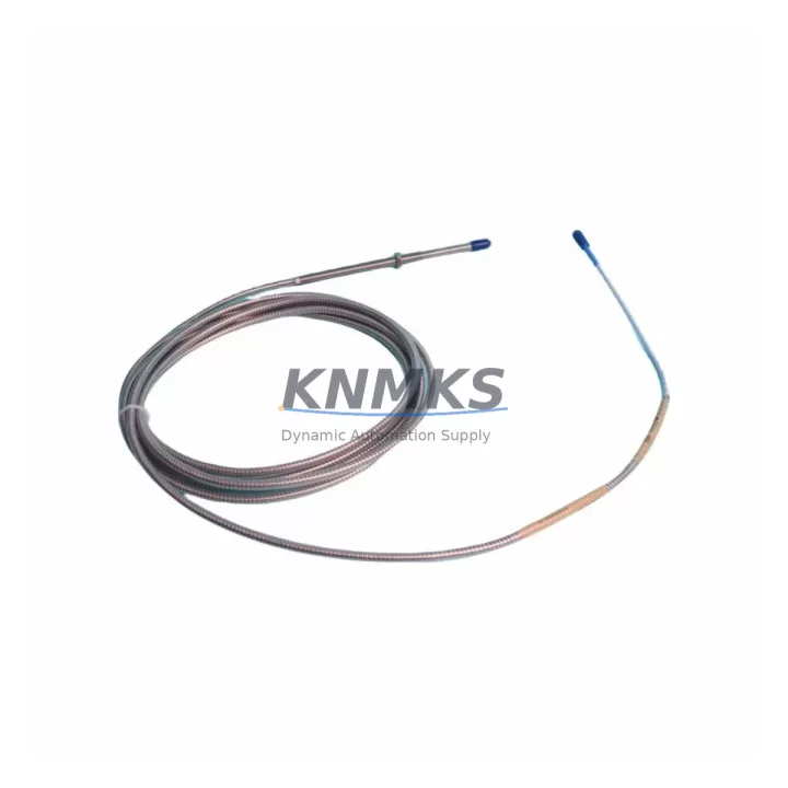
Bently Nevada 330104-05-13-10-01-00 Migration-Ready Proximity Transducer for Legacy 3300 XL Control Systems
The Bently Nevada 330104-05-13-10-01-00 is an eddy-current proximity transducer engineered for the 3300 XL Series monitoring platform. As legacy rotating machinery protection systems approach end-of-support cycles, this module serves as a verified migration-ready replacement for discontinued 3300 Series transducers, enabling engineers to restore full vibration and position monitoring capability without redesigning the existing signal chain. Whether you are recovering a failed channel on a critical compressor train, upgrading a turbine protection rack, or extending the service life of an aging condition monitoring system, the 330104-05-13-10-01-00 provides a direct, field-proven retrofit path.
This transducer operates within the standard Bently Nevada 3300 XL signal conditioning architecture, maintaining compatibility with the 3300 XL 8mm Extension Cable and the 3300 XL Proximitor® Sensor. The 330104 series uses a 5-metre armored cable assembly with a 10-32 UNF reverse-mount tip, producing a scale factor output consistent with the legacy 3300 Series, which means existing Proximitor® housings, junction boxes, and terminal strip wiring can typically be retained without modification. Before installation, engineers should confirm the gap voltage range, driver output impedance, and cable length against the existing system documentation to ensure the replacement channel will calibrate correctly within the 3500 Series rack or legacy 3300 rack as applicable.
Migration Compatibility Table
| Parameter | 330104-05-13-10-01-00 (This Unit) | Legacy / Replaced Models | Notes |
|---|---|---|---|
| Series | 3300 XL 8mm | 3300 8mm / 3300 5mm | Verify tip diameter before installation |
| Cable Length | 5 m (16.4 ft) | Varies (3 m / 5 m / 9 m) | Match to existing conduit run; extension cable may be required |
| Mounting Thread | 10-32 UNF Reverse Mount | 10-32 UNF / M10 | Confirm bracket thread before ordering |
| Scale Factor | 7.87 V/mm (200 mV/mil) | 7.87 V/mm | Compatible with existing Proximitor® calibration |
| Supply Voltage | -24 VDC (from Proximitor®) | -24 VDC | No power supply change required |
| Output Signal | -2 VDC to -18 VDC | -2 VDC to -18 VDC | Direct drop-in for existing DCS/rack input cards |
| Communication / Protocol | Analog (4–20 mA / voltage) | Analog | No protocol migration required |
| Installation Space | Standard 8mm probe body | 8mm probe body | Fits existing probe holder without machining |
| Firmware / Configuration | None (passive transducer) | None | No firmware update required |
| Support terms | support terms confirmed by quotation — covers manufacturing defects and signal performance under specified operating conditions | ||
Retrofit Planning for Existing Automation Systems
Successful integration of the 330104-05-13-10-01-00 into a running plant begins well before the maintenance window opens. The first step is a full channel audit of the existing 3300 XL Proximitor® Sensor associated with the failed or aging transducer. Technicians should record the current gap voltage at the Proximitor® output terminal, verify the driver supply rail at -24 VDC, and document the terminal strip labeling inside the junction box. If the plant uses a 3500/42M Proximitor® Monitor or a 3500/40M Proximitor® Monitor in the protection rack, the channel configuration — including alert and danger setpoints, full-scale range, and OK relay logic — must be exported from the rack configuration software before any hardware is disturbed.
Cable routing is a common source of delay during proximity transducer retrofits. The 330104-05-13-10-01-00 ships with a 5-metre integral cable, but many installations require an additional 3300 XL Extension Cable to bridge the distance between the probe tip and the Proximitor® housing mounted on the machinery skid or in the control cabinet. Confirm the total cable length against the driver’s specified range; exceeding the maximum combined cable length will shift the gap voltage curve and invalidate the existing calibration. Where conduit fill is already at capacity, a slim-profile cable gland or a re-routed cable tray segment may be necessary.
For plants running a hybrid architecture — where the 3300 XL transducer feeds both a legacy 3300 Series rack and a newer 3500 Series rack in parallel — engineers should verify that the Proximitor® output impedance is compatible with both input cards simultaneously. In some configurations, a signal isolator or a passive signal splitter is inserted between the Proximitor® output and the two rack inputs to prevent ground loop interference and maintain measurement accuracy across both monitoring channels. This is particularly important when the 3500 rack is connected to a DCS historian or a safety instrumented system that requires a clean, isolated 4–20 mA signal.
HMI screen updates are often overlooked during transducer replacements. If the plant SCADA or DCS uses tag-based faceplate displays tied to the channel engineering units, a brief configuration review should confirm that the new transducer’s scale factor matches the tag’s EU conversion. In most 3300 XL installations the scale factor is unchanged, so no HMI reconfiguration is required — but this should be verified against the existing loop documentation before the system is returned to service. Similarly, if the plant uses a System 1 Evolution condition monitoring platform connected to the 3500 rack, the channel should be re-baselined after installation to establish a new vibration reference for trend analysis.
Downtime Control During System Migration
Minimizing unplanned downtime during a proximity transducer replacement requires a structured pre-outage preparation process. Before the maintenance window, the replacement 330104-05-13-10-01-00 should be bench-tested using a calibrated driver and a reference target to confirm the gap voltage curve matches the published specification. This pre-shipment functional test — which is performed on every unit before dispatch — reduces the risk of discovering a defective replacement only after the original transducer has been removed from the machine.
During the outage, the recommended sequence is: (1) record the existing gap voltage and OK status at the Proximitor® terminal before disconnecting the original transducer; (2) remove the original probe and extension cable assembly, noting the probe tip-to-target gap measurement; (3) install the 330104-05-13-10-01-00 and set the initial gap to match the recorded value; (4) reconnect the Proximitor® and verify the output voltage falls within the linear range; (5) confirm the OK relay closes and the rack channel returns to normal status before releasing the machine for restart.
If the plant protection philosophy requires continuous monitoring during the replacement — for example, on a machine that cannot be taken offline — a temporary bypass relay or a channel inhibit function within the 3500 rack can be used to suppress the danger output while the transducer is being changed. This approach preserves the control logic and prevents a spurious trip from propagating to the emergency shutdown system. The inhibit should be logged in the plant management of change system and removed immediately after the new transducer is verified in service. Keeping a spare 330104-05-13-10-01-00 in the plant storeroom as a critical spare reduces the mean time to repair for future failures and supports the plant’s spare parts lifecycle management strategy.
Retrofit Support FAQ
Q1: Is the 330104-05-13-10-01-00 a direct replacement for the discontinued 330104-05-13-10-00-00?
A: Yes. The 330104-05-13-10-01-00 is the current production revision of the 330104-05-13-10-00-00. The physical dimensions, mounting thread, cable length, scale factor, and output voltage range are identical. No wiring changes or Proximitor® reconfiguration are required for a direct swap.
Q2: What wiring checks are required before installation?
A: Verify the Proximitor® supply voltage (-24 VDC ±1 VDC), confirm the terminal strip polarity (shield, driver, and output conductors), and check that the cable shield is grounded at one end only — typically at the Proximitor® housing. Dual-grounded shields are a common source of noise and OK relay instability after transducer replacement.
Q3: Does this unit ship with a functional test certificate?
A: Yes. Every 330104-05-13-10-01-00 dispatched from our warehouse is tested against the Bently Nevada published specification before shipment. A test record confirming gap voltage linearity and OK relay function is included with the unit. Stock is available for same-week dispatch.
Q4: What support terms coverage applies?
A: All units are covered by a support terms confirmed by quotation from the date of shipment. The support terms covers manufacturing defects and signal performance deviations under the specified operating conditions. Support requests are processed directly — contact our technical team with the unit serial number and a description of the fault.
© 2026 KNMKS. All rights reserved.
Original Source: https://knmks.com
Contact: admin@knmks.com | +86 18359268345
Product Identification
- Brand / Ecosystem
-
Bently Nevada
Bently Nevada - Model / Series
-
330104-05-13-10-01-00
Bently Nevada 3300 XL / 3301 Series - Product Family
- Sensors
- Availability Status
- Available on request after model and quantity confirmation
- Inquiry Type
- B2B RFQ, replacement inquiry and project spare-part request
- Pre-Quote Check
- Exact SKU, brand, series, quantity, nameplate photos and destination country are checked before quotation
System Path
Where this product fits in the KNMKS automation structure.
Specification & Inquiry Focus
- Sensor range
- Photoelectric, proximity and process sensors
- Common needs
- Output type, distance and connector
- Project support
- Machine detection and replacement inquiry
Buyer Confirmation
Information KNMKS checks before replying.
- Exact model
- 330104-05-13-10-01-00
- Brand / ecosystem
- Bently Nevada
- Product family
- Sensors
- Application note
- Replacement, maintenance, project build or spare-part list
- Useful photos
- Nameplate, installed unit, cabinet layout or connector side
- Delivery details
- Quantity, destination country and target schedule
Document Support
Files and notes can be confirmed during quotation.
- Product photos or nameplate confirmation when available
- Packing and delivery notes before quotation confirmation
- Support scope and delivery terms confirmed per inquiry
- Export document coordination for qualified B2B requests
Inquiry Support
- NPN/PNP, analog and digital output checking
- Connector and cable compatibility review
- Fast inquiry support for maintenance teams
What to Send Us
- Brand and exact model number: Bently Nevada 330104-05-13-10-01-00
- Quantity and required delivery time
- Application, replacement requirement or nameplate photo
- Destination country and shipping preference
RFQ Preparation
This is a product inquiry page built for RFQ communication.
Fast Model Check
Send this model to KNMKS for confirmation.
Include quantity, destination country and photos if this is a maintenance replacement. The inquiry will be saved with a reference number after submission.
Brand & Compatibility Note
KNMKS displays automation product information for well-known industrial brand ecosystems and compatible replacement references. Brand names are used for product identification and compatibility reference only; final availability and commercial terms are confirmed per quotation.
 Manufacturing
 Machine Tools
 Packaging
 Energy & Power



 PLCs & Controllers
 HMI & Displays
 Servo Systems
 Variable Frequency Drives