
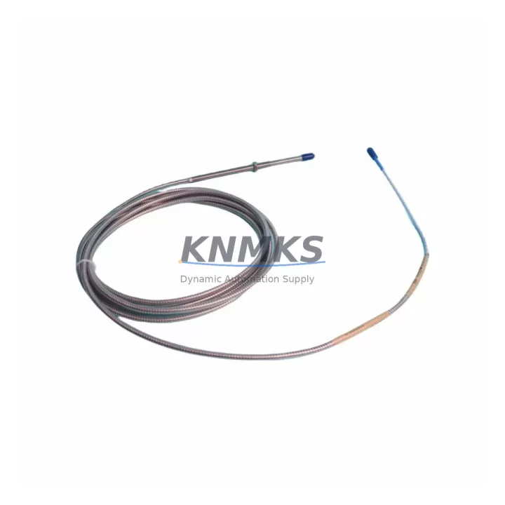
Overview
Bently Nevada 330104-05-11-50-02-CN Migration-Ready Proximity Transducer for Legacy Control Systems
The Bently Nevada 330104-05-11-50-02-CN is a 3300 XL Series proximity transducer engineered for direct replacement and retrofit integration into aging vibration monitoring and machinery protection systems. As legacy Bently Nevada 3300 Series installations approach end-of-service life, plant engineers and maintenance teams increasingly rely on this SKU to restore system integrity without requiring full platform overhauls. Whether you are replacing a failed unit on a critical rotating machine or executing a planned upgrade of your condition monitoring infrastructure, the 330104-05-11-50-02-CN delivers the electrical and mechanical compatibility needed to minimize engineering risk and reduce unplanned downtime.
This transducer operates within the standard 3300 XL proximity system architecture, maintaining full signal chain compatibility with existing Bently Nevada 3300 XL extension cables, driver electronics, and monitoring rack modules. The 5-meter armored cable assembly, 8 mm probe tip diameter, and -18 VDC nominal bias voltage output are consistent with the original 330104 series specification, allowing direct substitution in most installations without rewiring terminal blocks or reconfiguring monitor channel parameters. Before installation, engineers should verify the gap voltage setting at the driver output, confirm the probe-to-target material pairing, and validate the linear range against the existing calibration record stored in the monitoring system.
When integrating the 330104-05-11-50-02-CN into a legacy control cabinet, particular attention should be paid to the junction box terminal assignments. The coaxial signal cable shield must be grounded at one end only to prevent ground loop interference, and the extension cable connector seating should be inspected for corrosion or mechanical damage before energizing the circuit. If the existing installation uses a Bently Nevada 3300/16 or 3300/20 monitor card, the channel configuration—including full-scale range, alert and danger setpoints, and time constant—should be documented and re-entered after the transducer swap to ensure alarm logic continuity.
For facilities managing a broader migration from the 3300 platform toward the System 1 or 3500 Series architecture, the 330104-05-11-50-02-CN serves as a bridging component that preserves measurement continuity during phased upgrades. In this context, it is commonly deployed alongside the Bently Nevada 3500/42M vibration monitor module, which accepts the same proximity transducer signal format and supports both legacy and modern I/O configurations. Facilities transitioning communication protocols from proprietary Bently Nevada serial links to Modbus TCP or OPC-UA will find that retaining proven transducer hardware at the field level reduces the number of variables introduced during the protocol migration, simplifying commissioning and fault isolation.
Retrofit planning for control cabinets housing multiple measurement points should also account for the Bently Nevada 3500/15 power supply module, which provides the regulated -24 VDC required by the 3300 XL transducer circuit. Confirming available power budget before adding replacement transducers to an existing rack prevents nuisance trips caused by supply rail sag under increased load. Similarly, if the retrofit scope includes expanding I/O coverage to previously unmonitored bearing positions, the addition of a Bently Nevada 3500/22M transient data interface module allows high-resolution waveform capture without disrupting the steady-state monitoring channels already in service.
In installations where the 330104-05-11-50-02-CN replaces a transducer that was part of a turbine supervisory instrumentation (TSI) loop, the replacement procedure should include a functional verification of the Keyphasor signal path. The Keyphasor reference, typically provided by a dedicated Bently Nevada 330180 series transducer mounted on the shaft, must remain synchronized with the vibration channels to preserve phase-referenced amplitude and dynamic data accuracy. Any change in Keyphasor gap voltage or signal polarity introduced during adjacent transducer work should be corrected before returning the machine to service.
All units of the 330104-05-11-50-02-CN supplied by KNMKS are sourced from verified inventory channels and undergo pre-shipment functional testing to confirm bias voltage output, sensitivity coefficient, and cable continuity. Each unit is covered by a support terms confirmed by quotation against manufacturing defects and is shipped with documentation supporting traceability requirements for regulated industries including petrochemical, power generation, and offshore production.
Migration Compatibility Table
| Parameter | 330104-05-11-50-02-CN Specification | Legacy 3300 Series Compatibility | Retrofit Notes |
|---|---|---|---|
| Probe Tip Diameter | 8 mm | Direct fit for standard 3300 XL probe mounts | Verify thread engagement depth in existing bracket |
| Cable Length | 5 m (armored) | Compatible with 3300 XL extension cable assemblies | Confirm total system cable length within driver spec |
| Bias Voltage Output | -10 VDC nominal (at calibrated gap) | Compatible with 3300/16, 3300/20, 3500/42M monitors | Re-verify gap after installation; target -10 ± 0.5 VDC |
| Sensitivity | 200 mV/mil (7.87 V/mm) | Matches 3300 XL system calibration standard | No channel rescaling required for direct replacement |
| Supply Voltage | -24 VDC (from driver/monitor) | Supplied by 3500/15 or equivalent power module | Confirm power budget before adding channels |
| Communication / Signal | Analog voltage (coaxial) | Compatible with Modbus RTU via 3500 gateway modules | Protocol migration requires 3500 series rack integration |
| Installation Space | Standard 3300 XL probe body envelope | Fits existing probe holder and conduit entry | Check clearance for armored cable bend radius |
| Firmware / Configuration | No embedded firmware (passive transducer) | Monitor channel config retained from previous unit | Re-enter setpoints and time constants after swap |
| Support terms | support terms confirmed by quotation — Covers manufacturing defects; includes pre-shipment functional test report | ||
Retrofit Planning for Existing Automation Systems
A successful retrofit using the 330104-05-11-50-02-CN begins with a thorough audit of the existing measurement loop. Technicians should document the current gap voltage, alert and danger setpoints, channel time constants, and any custom scale factors programmed into the monitor before removing the failed or obsolete transducer. This baseline record becomes the reference for post-installation verification and is essential if the site operates under a management of change (MOC) procedure.
In multi-channel installations, the replacement transducer is typically installed alongside existing Bently Nevada 3300 XL extension cables that remain serviceable. If the extension cable shows signs of jacket damage, connector wear, or impedance mismatch, it should be replaced concurrently to avoid introducing a new failure point into the restored measurement loop. The Bently Nevada 330130 series extension cables are the standard pairing for the 330104 probe family and maintain the coaxial impedance specification required for accurate signal transmission over the full cable run.
For control cabinets undergoing broader modernization, the 330104-05-11-50-02-CN is frequently installed as part of a rack-level upgrade that also introduces a Bently Nevada 3500/42M dual-channel vibration monitor to replace aging 3300-series monitor cards. This combination preserves field wiring and probe hardware investments while delivering improved diagnostics, expanded alarm logic, and support for digital communication to the plant DCS or historian. Where the existing DCS interface relies on 4–20 mA analog outputs from the monitor rack, the 3500/42M supports this output format natively, eliminating the need for signal conditioning modules during the transition.
Sites that include shaft absolute vibration measurement in their TSI scope will also need to verify the seismic transducer channel configuration. The proximity transducer measures shaft relative vibration; combining its output with a seismic signal from a velocity or accelerometer channel—such as those supported by the Bently Nevada 3500/46M six-channel monitor—provides the shaft absolute vibration value required by API 670 for turbine protection. Ensuring both channels are correctly configured and phase-aligned before machine restart is a critical commissioning step that should be included in the pre-startup checklist.
Downtime Control During System Migration
Minimizing production impact during a proximity transducer replacement requires advance preparation and a clearly sequenced execution plan. Before the maintenance window opens, the replacement 330104-05-11-50-02-CN should be bench-tested to confirm bias voltage output and cable continuity, and all required tools, torque specifications, and terminal wiring diagrams should be staged at the work site. Having a pre-tested spare unit on hand eliminates the risk of discovering a defective replacement after the machine has already been taken offline.
During the swap, the original program logic in the associated safety or control system should not be modified. Monitor channel parameters—including full-scale range, alert setpoints, danger setpoints, and time constants—should be recorded before power-down and restored from the documented baseline after the new transducer is installed and gapped. This approach protects the integrity of the control logic and avoids inadvertent changes to alarm thresholds that could affect machine protection during the post-maintenance run-up.
After installation, the gap voltage should be verified with the machine stationary before energizing the full monitoring loop. A gap reading within the specified linear range confirms correct probe-to-target spacing and validates the mechanical installation. The monitor channel should then be observed through a complete machine start sequence to confirm that vibration readings are stable, alarm logic is functioning, and no spurious trips are generated by the new transducer. Documenting the as-left gap voltage and initial vibration baseline provides a reference for future condition trending and supports the site’s predictive maintenance program.
For facilities with redundant monitoring configurations, the replacement can often be performed on one channel while the parallel channel remains in service, further reducing the risk of unprotected operation during the maintenance activity. Coordinating the transducer replacement with the site’s existing permit-to-work and isolation procedures ensures that all safety requirements are met and that the restored measurement loop is formally accepted before the machine returns to normal operation.
Retrofit Support FAQ
Q: Is the 330104-05-11-50-02-CN a direct replacement for other 330104 series variants?
A: The 330104-05-11-50-02-CN is directly interchangeable with other 330104 series proximity transducers that share the same probe tip diameter, cable length, and sensitivity specification. Variants with different cable lengths (e.g., 330104-05-11-50-01 or -03 suffixes) may require extension cable length adjustment to maintain the total system cable length within the driver’s specified range. Always confirm the full part number against the existing installation record before ordering.
Q: What commissioning steps are required after installing the replacement transducer?
A: After mechanical installation, set the probe gap to achieve a bias voltage of -10 VDC ± 0.5 VDC at the driver output with the machine stationary. Restore all monitor channel parameters from the pre-maintenance baseline record. Perform a functional check of alert and danger alarm outputs before releasing the machine for start-up. Record the as-left gap voltage and initial vibration reading in the site maintenance log.
Q: Can this transducer be used with non-Bently Nevada monitor systems?
A: The 330104-05-11-50-02-CN outputs a standard eddy-current proximity signal compatible with any monitor that accepts a -24 VDC powered, 200 mV/mil sensitivity coaxial input. Compatibility with third-party monitors should be verified against the monitor manufacturer’s input specification before installation. Signal conditioning may be required if the third-party system expects a different sensitivity or bias voltage range.
Q: What does the support terms confirmed by quotation cover, and what is the typical lead time?
A: The support terms confirmed by quotation cover manufacturing defects identified under normal operating conditions and includes a pre-shipment functional test report for each unit. Units availability confirmed by RFQ at KNMKS are typically dispatched within 1–3 business days. For urgent requirements, expedited shipping options are available. Contact admin@knmks.com or call +86 18359268345 to confirm current inventory availability and delivery schedule.
© 2026 KNMKS. All rights reserved.
Original Source: https://knmks.com
Contact: admin@knmks.com | +86 18359268345
Product Identification
- Brand / Ecosystem
-
Bently Nevada
Bently Nevada - Model / Series
-
330104-05-11-50-02-CN
Bently Nevada 3300 XL / 3301 Series - Product Family
- Sensors
- Availability Status
- Available on request after model and quantity confirmation
- Inquiry Type
- B2B RFQ, replacement inquiry and project spare-part request
- Pre-Quote Check
- Exact SKU, brand, series, quantity, nameplate photos and destination country are checked before quotation
System Path
Where this product fits in the KNMKS automation structure.
Specification & Inquiry Focus
- Sensor range
- Photoelectric, proximity and process sensors
- Common needs
- Output type, distance and connector
- Project support
- Machine detection and replacement inquiry
Buyer Confirmation
Information KNMKS checks before replying.
- Exact model
- 330104-05-11-50-02-CN
- Brand / ecosystem
- Bently Nevada
- Product family
- Sensors
- Application note
- Replacement, maintenance, project build or spare-part list
- Useful photos
- Nameplate, installed unit, cabinet layout or connector side
- Delivery details
- Quantity, destination country and target schedule
Document Support
Files and notes can be confirmed during quotation.
- Product photos or nameplate confirmation when available
- Packing and delivery notes before quotation confirmation
- Support scope and delivery terms confirmed per inquiry
- Export document coordination for qualified B2B requests
Inquiry Support
- NPN/PNP, analog and digital output checking
- Connector and cable compatibility review
- Fast inquiry support for maintenance teams
What to Send Us
- Brand and exact model number: Bently Nevada 330104-05-11-50-02-CN
- Quantity and required delivery time
- Application, replacement requirement or nameplate photo
- Destination country and shipping preference
RFQ Preparation
This is a product inquiry page built for RFQ communication.
Fast Model Check
Send this model to KNMKS for confirmation.
Include quantity, destination country and photos if this is a maintenance replacement. The inquiry will be saved with a reference number after submission.
Brand & Compatibility Note
KNMKS displays automation product information for well-known industrial brand ecosystems and compatible replacement references. Brand names are used for product identification and compatibility reference only; final availability and commercial terms are confirmed per quotation.
 Manufacturing
 Machine Tools
 Packaging
 Energy & Power



 PLCs & Controllers
 HMI & Displays
 Servo Systems
 Variable Frequency Drives